Behringer DIGITAL RACK MIXER X32 RACK User Manual - Page 40
Channel Indicator, Show Indicator, Scene Name/Number, USB Recorder File, Clock, Main Content
 |
View all Behringer DIGITAL RACK MIXER X32 RACK manuals
Add to My Manuals
Save this manual to your list of manuals |
Page 40 highlights
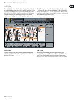
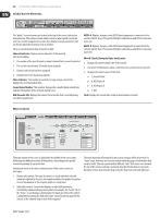
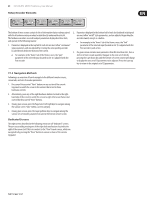
40 X32 DIGITAL MIXER Preliminary User Manual Global Screen Elements Ch01 FatSnare 01 OpeningScene 02: next home con g 0:00 gate - 0:00 dyn A: S16 B: - eq 15:33 A: 48K C: XUF : 15 sends main The "global" screen elements are located at the top of the screen, laid out in a horizontal row. They always remain visible no matter what specific screen the user has currently navigated to, because they displays console parameters that are always important to keep in view at all times. These screen elements include, from left to right: Channel Indicator: Displays various elements of the currently selected, including: 1. The number of the specific input or output channel that is currently selected 2. The custom channel name (if one has been assigned) 3. Channel color (if one has been assigned) 4. Channel icon (if one has been assigned) Show Indicator: This number, presented in a large orange colored font, displays the currently loaded show. Scene Name/Number: Thus number, displayed in a smaller black colored font, indicates the number of the currently loaded scene. USB Recorder File: Displays the name of the active file that is currently being recorded or played back. AES50-A: Displays, by name, what AES50 based equipment is connected to the console's AES50-A port. The green LED lights solid when a valid AES50 connection is present. AES50-B: Displays, by name, what AES50 based equipment is connected to the console's AES50-B port. The green LED lights solid when a valid AES50 connection is present. Word Clock/Sample Rate Indicator: 1. Displays the current sample rate of the console. 2. The green LED illuminates when a valid internal or external clock is present. 3. Displays the current source of the clock: • L: Internal Clock • A: AES50 port A • B: AES50 port B • C: XUF Clock: Displays the current time of day in hours:minutes:seconds. Main Content 01 01: home con g 0:00 gate clip -6 48V In -12 Reverse -18 -24 -30 -36 Link Lo Cut Source OFF -42 +0.0 dB 2.0 Hz Input 01 -48 Input 02 -54 Input 03 Input 04 Gain Lo Cut Input 05 Input 06 - 0:00 dyn t B: - C: XUF 14:11 : 37 eq sends main Insert Position Delay Pre Ins 0.3 ft 0.10 m 0.03 ms Delay Post Insert OFF InsFX 1L InsFX 1R InsFX 2L InsFX 2R InsFX 3L InsFX 3L Gain Lo Cut Source Delay Ins Pos Insert The main content of the screen is displayed in the middle of the screen and is divided up into different sections of information, depending on the specific screen being shown at any given time. Information shown in the main content portion of the screen consists of two types: 1. Display-only content: This type of content is a visual indication only and cannot be adjusted by the user. An example would be the graphical response curve of an equalizer or the response graph of a compressor. 2. Adjustable content: Content that displays an adjustable parameter, controlled by a dedicated top-panel control. For example, the "home" tab of the "home" screen displays a knob graphic for input gain (trim). This control is adjustable by turning the dedicated "gain" control on the top panel of the console, in the Channel Strip section of the top panel. The most important information for any screen category will be located on it's "home" page. However, most screens contain alternate pages of information that are also useful. They are represented by different "tabs" that can be seen towards the top of the screen. Each tab is named to describe the functions it represents. Navigate to these alternate tabs by pressing the Page Select left and right keys.
-
 1
1 -
2
-
3
-
4
-
5
-
6
-
7
-
8
-
9
-
10
-
11
-
12
-
13
-
14
-
15
-
16
-
17
-
18
-
19
-
20
-
21
-
22
-
23
-
24
-
25
-
26
-
27
-
28
-
29
-
30
-
31
-
32
-
33
-
34
-
 35
35 -
 36
36 -
 37
37 -
 38
38 -
 39
39 -
 40
40 -
 41
41 -
 42
42 -
 43
43 -
 44
44 -
 45
45 -
46
-
47
-
48
-
49
-
50
-
51
-
52
-
53
-
54
-
55
-
56
-
57
-
58
-
59
-
60
-
61
-
62
-
63
-
64
-
65
-
66
-
67
-
68
-
69
-
70
 |
 |
