Behringer FBQ800 Quick Start Guide - Page 5
MINIFBQ FBQ800 Controls
 |
View all Behringer FBQ800 manuals
Add to My Manuals
Save this manual to your list of manuals |
Page 5 highlights
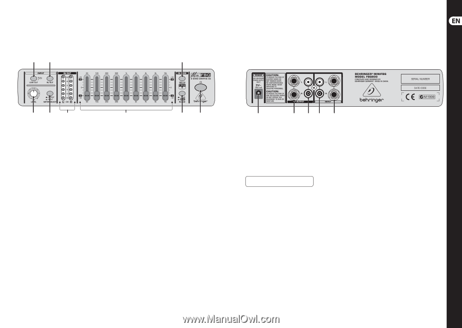
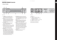
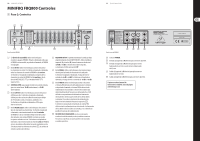
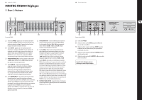
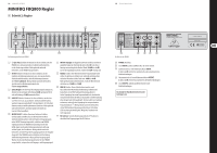
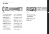
8 MINIFBQ FBQ800 MINIFBQ FBQ800 Controls (EN) Step 2: Controls (4) (2) (8) 9 Quick Start Guide (3) (5) (6) FBQ800 front panel (9) (7) (1) (1) � (POWER) button: To turn the FBQ800 on and off, use this button, pushed in and illuminated: The FBQ800 is on. Not pushed in and not illuminated: The FBQ800 is off. (2) IN/OUT button: To activate or, alternatively deactivate control elements, use this button, pushed in and illuminated: The FBQ800 activates all control elements. Not pushed in and not illuminated: The FBQ800 deactivates most control elements. However, you can use the METER SELECT button (5) and the IN/OUT meter (6). (3) LEVEL CONTROL: To adjust the level of the input signal, turn this control toward -12 dB (minimum setting) or, alternatively +12 dB (maximum setting). (4) LOW CUT button: To manage the low-cut filter, use this button, pushed in and illuminated: The low-cut filter eliminates sounds that are below 75 Hz (floor rumble, room resonance, and mains hum, for example). Not pushed in and not illuminated: The low-cut filter does not eliminate any sounds. (5) METER SELECT button: To select the type of signal you want to monitor, use this button, pushed in and illuminated: Monitor the input signal as soon as this signal enters the FBQ800. The FBQ800 does not apply the LEVEL control or any other control elements to the input signal that you monitor. Not pushed in and not illuminated: Monitor the output signal as soon as this signal leaves the FBQ800. The FBQ800 applies all control elements to the output signal that you monitor. However, if you deactivated most of the control elements (2), the input signal and the output signal are the same. (6) IN/OUT METER: To monitor the level of the signal that you selected with the METER SELECT button, use this stereo meter. Both the left (L) and right (R) sides of this meter share the same decibel scale (-24 dB to +6 dB). If the signal level is too high, the CLIP LED illuminates. (7) RANGE button: To select a range for the EQ faders, use this button, pushed in and illuminated: The fader range extends from -6 dB to +6 dB. Not pushed in and not illuminated: The fader range extends from -12 dB to +12 dB. (8) FBQ IN button: To manage the FBQ Feedback Detection System, use this button, pushed in and illuminated: The FBQ Feedback Detection System is activated. If the signal level is high in a frequency band, the relevant fader LED illuminates brightly. In addition, all other fader LEDs are dimmed. To reduce the potential for feedback, cut the signal in the relevant frequency band (9). Not pushed in and not illuminated: The FBQ Feedback Detection System is not activated. Fader LEDs illuminate with identical brightness. They do not identify possible feedback frequencies. (9) EQ SECTION: If you activated all control elements (2), the input signal travels to the EQ section. (10) FBQ800 rear panel (13) (14) (11) (12) (10) POWER connector. (11) RCA INPUT, L (left) and R (right): for RCA plugs (12) ¼" TRS INPUT, L (left) and R (right): for TRS (balanced) or, alternatively TS (unbalanced) plugs. (13) ¼" TS OUTPUT, L (left) and R (right): for TS (unbalanced) plugs (14) RCA OUTPUT, L (left) and R (right): for RCA plugs. Check Out behringer.com for Full Manual
-
 1
1 -
 2
2 -
 3
3 -
 4
4 -
 5
5 -
 6
6 -
 7
7 -
 8
8 -
 9
9 -
 10
10 -
 11
11 -
12
-
13
-
14
 |
 |