Behringer SHARK FBQ100 Manual - Page 11
Specifications, Rackmount Optional - canada
 |
View all Behringer SHARK FBQ100 manuals
Add to My Manuals
Save this manual to your list of manuals |
Page 11 highlights
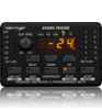
11 SHARK FBQ100 User Manual 4. Specifications Audio Inputs Connectors XLR and ¼" TRS jack Impedance 6 kΩ balanced, 3 kΩ unbalanced Nominal operating level Microphone or line level source (switchable) Max. input level +19 dBu at microphone level and line level Audio Outputs Connectors XLR and ¼" jack Impedance 60 Ω balanced, 30 Ω unbalanced Nominal operating level Microphone level source or +4 dBu (switchable) Max. output level +20 dBu at +4 dBu nominal level, -12 dBu at microphone level System Specifications Frequency response Noise THD 10 Hz to 21 kHz > 92 dB at line level, unweighted, 22 Hz to 22 kHz > 89 dB at microphone level, unweighted, 22 Hz to 22 kHz 0.007% typ. @ +4 dBu, 1 kHz, gain 1 5. Rackmount (Optional) With the available rackmount (optional) you have the possibility to place five SHARKs on two units of space in your rack. ◊ Before you begin with the work, please disconnect the Power Supply Units from the SHARKs! To mount the SHARKs on the rackmount you should use the supplied screws (type M3). You need two screws to fix one FBQ100 onto the rackmount. In the bottom of your SHARK you will find two little threads. You have to position the single SHARKs on the rackmount, so that the threads correspond to the cutouts of the rackmount (see fig. 5.1). Now you can fix the FBQ100 onto the rackmount. Just take a cross-point screwdriver and tighten both screws loosely. After you have fixed all SHARKs on the rackmount, you can adjust the devices and tighten all screws solidly. Bottom FBQ100 Thread 1 Thread 2 Cutout 1 Cutout 2 Front Rackmount (Bottom View) Digital Processing Converters 24-bit Sigma-Delta, 64/128-times oversampling Display Type 4-digit numeric LED display Power Supply Mains Voltages/Power Consumption USA/Canada 120 V~ 60 Hz 19 W U.K./Australia 240 V~ 50 Hz 20.5 W Europe 230 V~ 50 Hz 20 W Korea 220 V~ 50 Hz 20 W China 220 V~ 50 Hz 20 W Japan 100 V~ 50/60 Hz 18 W Fig. 5.1: Installation of the FBQ100 on the available rackmount (optional) ◊ Please, only use the supplied screws to install the SHARKs on the rackmount. Longer or thicker screws can damage the electronics inside of the device and doing so will void your warranty rights. You will need 2 units of space for the FBQ100 rackmount. For technical reasons a little gap remains above the rackmount. Physical Dimensions (H x W x D) Net Weight approx. 2.2 x 3.5 x 5.2" / 56 x 88 x 132 mm approx. 0.84 lbs / 0.38 kg BEHRINGER is constantly striving to maintain the highest professional standards. As a result of these efforts, modifications may be made from time to time to existing products without prior notice. Specifications and appearance may differ from those listed or illustrated.
-
 1
1 -
2
-
3
-
4
-
5
-
 6
6 -
 7
7 -
 8
8 -
 9
9 -
 10
10 -
 11
11 -
 12
12 -
 13
13
 |
 |