Behringer SHARK FBQ100 Manual - Page 5
Introduction - shark fbq1000
 |
View all Behringer SHARK FBQ100 manuals
Add to My Manuals
Save this manual to your list of manuals |
Page 5 highlights
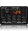
5 SHARK FBQ100 User Manual 1. Introduction 1.1 The concept With the SHARK FBQ100 you purchased a device that combines an automatic Feedback Destroyer using the ingenious search algorithms of our FEEDBACK DESTROYER FBQ1000, a variable Delay Line (adjustable in msec, feet and meter), a ULN (Ultra-Low Noise) microphone pre-amp with Phantom Power, an automatic Noise Gate, a variable Low Cut filter and a Compressor-all in one ultra-rugged and compact case. Still, the SHARK can be operated intuitively and expanded to a multi-channel system using another four SHARKs and an optionally available 19" rack mount kit. The SHARK's 24-bit A/D and D/A converters guarantee a precise reproduction of your program material. High volume levels and the use of ever more sophisticated monitoring systems with a multitude of speaker cabinets have led to a greater potential risk of feedback loops in sound reinforcement systems. So far, audio engineers have been using conventional 1/3-octave equalizers to suppress unwanted feedback. However, the individual filters of such an EQ, with their relatively wide bandwidth, have quite an impact on the sound image. With the BEHRINGER SHARK (minimum bandwidth: 1/60 of an octave) you are now free to either choose the trial and error method to suppress feedback with graphic equalizers, or to assign this task to the FBQ100, so that you can give your music your undivided attention. Using extremely narrow-bandwidth filters, the SHARK FBQ100 eliminates only unwanted feedback, without affecting your music. Please use the enclosed power supply to connect the unit to the mains. The supply complies with all applicable safety standards. ◊ Please note that all units must be grounded properly. For your own safety, you should never remove any ground connectors from electrical devices or power cords or render them inoperative. Further information can be found in chapter 3 "Installation". As a standard the audio inputs and outputs of the BEHRINGER SHARK FBQ100 are fully balanced. If possible, connect the unit to other devices in a balanced configuration to allow for maximum interference immunity. The automatic servo function detects unbalanced connections and compensates the level difference automatically (6 dB correction). 1.3 Control elements (1) (2) (3) (4) (5) Speaker Box Microphone (9) (6) (10) (7) (11) (8) (12) (13) Fig. 1.2: Front panel control elements of the FBQ100 Mixing Console Power Amp Fig. 1.1: Typical feedback loop 1.2 Before you begin Your SHARK was carefully packed in the factory and the packaging is designed to protect the unit from rough handling. Nevertheless, we recommend that you carefully examine the carton and its contents for any signs of physical damage, which may have occurred during transit. ◊ If the unit is damaged, please do not return it to BEHRINGER, but notify your dealer and the shipping company immediately, otherwise claims for damage or replacement may not be granted. Shipping claims must be made by the consignee. The optionally available rack mount kit allows you to mount your BEHRINGER SHARK in a standard 19" rack, together with another four SHARKs. The rack mount kit requires 2U of rack space. Be sure that there is enough air space around the unit for cooling and please do not place the SHARK on high-temperature devices such as power amps, etc. to avoid overheating. (1) The CLIP LEVEL METER shows you whether or not the digital circuitry is driven correctly. Any corrections can be made with the CLIP LEVEL control (2). Be sure that the CLIP LED won't light up. (2) The CLIP LEVEL control lets you adapt the internal gain optimally to the digital circuitry. If gain is too high (CLIP LED lights up), raise the CLIP LEVEL value by turning the control to the right (and vice versa). Thus, you can shift the operating level upwards/downwards. ◊ The CLIP LEVEL control does not affect the input/output levels, but adapts the audio signal as optimally as possible to the threshold of the digital circuitry. (3) These five LEDs symbolize the units of the parameters that can be adjusted on the display (4). (4) The 4-digit DISPLAY reads the absolute values of the adjusted parameters. (5) The FB-D FILTER STATUS LEDs display the status of each of the 12 individual filters. The SHARK uses four different filter modes: • Disabled filters (which can be re-enabled with the ACTIVE button). When a filter is off, its LED is not lit. • Free filters which automatically search for feedback frequencies and whose activity is shown by a flashing LED. • Set filters which can be reconfigured as free (searching) filters, when all filters are currently in use. • Permanently set filters which must be RESET to be reconfigured as free filters. Once a filter has been set, its LED lights up.
-
 1
1 -
 2
2 -
 3
3 -
 4
4 -
 5
5 -
 6
6 -
 7
7 -
 8
8 -
 9
9 -
 10
10 -
 11
11 -
12
-
13
 |
 |
