Behringer UB1222FX-PRO User Manual - Page 6
Control Elements And, Connectors - eurorack
 |
View all Behringer UB1222FX-PRO manuals
Add to My Manuals
Save this manual to your list of manuals |
Page 6 highlights
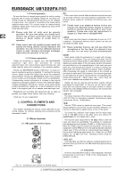
EURORACK UB1222FX-PRO 1.3.2 Initial operation Be sure that there is enough space around the unit for cooling purposes and to avoid over-heating. Please do not place your mixing console on high-temperature devices such as radiators or power amps. The console is connected to the mains via the supplied power cable. The console meets the required safety standards. Blown fuses must only be replaced by fuses of the same type and rating. + Please note that all units must be properly grounded. For your own safety, you should never remove any ground connectors from electrical devices or power cables, or render them inoperative. + Please ensure that only qualified people install and operate the mixing console. During installation and operation, the user must have sufficient electrical contact to earth, otherwise electrostatic discharges might affect the operation of the unit. 1.3.3 Online registration Please do remember to register your new BEHRINGER equipment right after your purchase by visiting www.behringer.com (alternatively www.behringer.de) and kindly read the terms and conditions of our warranty carefully. Should your BEHRINGER product malfunction, our goal is to have it repaired as quickly as possible. To arrange for warranty service, please contact the retailer from whom the equipment was purchased. Should your BEHRINGER dealer not be located in your vicinity, you may directly contact one of our subsidiaries. Corresponding contact information is included in the original equipment packaging (Global Contact Information/European Contact Information). Should your country not be listed, please contact the distributor nearest you. A list of distributors can be found in the support area of our website (www.behringer.com). Registering your purchase and equipment with us helps us process your repair claims quicker and more efficiently. Thank you for your cooperation! 2. CONTROL ELEMENTS AND CONNECTORS This chapter describes the various control elements of your mixing console. All controls, switches and connectors will be discussed in detail. 2.1 Mono channels 2.1.1 Microphone and line inputs MIC Each mono input channel offers a balanced microphone input via the XLR connector and also features a switchable +48 V phantom power supply for condenser microphones (see rear panel). + Please mute your playback system before you activate the phantom power supply to prevent switch-on thumps being directed to your loudspeakers. Please also note the instructions in chapter 2.5 “Rear view of UB1222FX-PRO”. LINE IN Each mono input also features a balanced line input on a 1/4" connector. Unbalanced devices (mono jacks) can also be connected to these inputs. + Please remember that you can only use either the microphone or the line input of a channel at any one time. You can never use both simultaneously! INSERT Insert points enable the processing of a signal with dynamic processors or equalizers. They are sourced pre-fader, pre-EQ and pre-aux send. Unlike reverb or other effects devices, whose signals are usually added to the dry signal, dynamic processors are most effective on the complete signal. In this case, aux send paths are a less-than-perfect solution. It is better to interrupt the signal path and insert a dynamic processor and/or equalizer. After processing, the signal is routed back to the console at precisely the same point it left. However, the channel signal path is interrupted only if a plug is inserted into the corresponding jack (stereo phone plug: tip = signal output; ring = return input). All mono input channels are equipped with inserts. Inserts can also be used as pre-EQ direct outputs, without interrupting the signal path. To this end, you will need a cable fitted with mono phone plugs on the tape machine or effects device end, and a bridged stereo phone plug on the console side (tip and ring connected). LOW CUT The mono channels of the mixing consoles have a high-slope LOW CUT filter for eliminating unwanted, low-frequency signal components (80 Hz, 18 dB/octave). TRIM Use the TRIM control to adjust the input gain. This control should always be turned fully counter-clockwise whenever you connect or disconnect a signal source to one of the inputs. The scale has 2 different value ranges: the first value range (+10 to +60 dB) refers to the MIC input and shows the amplification for the signals fed in there. The second value range (+10 to -40 dBu) refers to the line input and shows its sensitivity. The settings for equipment with standard line-level signals (-10 dBV or +4 dBu) look like this: While the TRIM control is turned all the way down, connect your equipment. Set the TRIM control to the external devices’ standard output level. If that unit has an output signal level display, it should show 0 dB during signal peaks. For +4 dBu, turn up TRIM slightly, for -10 dBV a bit more. Tweaking is done using the LEVEL SET LED. LEVEL SET This LED lights up when the optimum operating signal level is achieved. During normal use, this LED should only light up during signal peaks. 2.1.2 Equalizer All mono input channels include a 3-band equalizer. All bands provide boost or cut of up to 15 dB. In the central position, the equalizer is inactive. Fig. 2.1: Connectors and controls of mic/line inputs 6 2. CONTROL ELEMENTS AND CONNECTORS
-
 1
1 -
 2
2 -
 3
3 -
 4
4 -
 5
5 -
 6
6 -
 7
7 -
 8
8 -
 9
9 -
 10
10 -
 11
11 -
 12
12 -
13
-
14
-
15
 |
 |
