Behringer UB1222FX-PRO User Manual - Page 8
Stereo channels, 3 Connector panel and main - eurorack mixer
 |
View all Behringer UB1222FX-PRO manuals
Add to My Manuals
Save this manual to your list of manuals |
Page 8 highlights
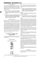
EURORACK UB1222FX-PRO 2.2 Stereo channels 2.2.1 Channel inputs 2.3 Connector panel and main section Whereas it was useful to trace the signal flow from top to bottom in order to gain an understanding of the channel strips, we now look at the mixing console from left to right. The signals are, so to speak, collected from one point on each of the channel strips and then routed to the main section all together. 2.3.1 Monitor send and FX send channels Fig. 2.5: Stereo channel inputs Each stereo channel features two line-level inputs on 1/4" connectors for left and right channels. Channels 9/10 and 11/12 can also be used in mono if you only use the connector labeled “L.” Both channels 5/6 and 7/8 feature an additional balanced XLR input for microphones with available +48 V phantom power. All stereo channel strips have a TRIM control for level setting. In those channels in which a mic input is present in the channel, the TRIM control has two scales: just like in the mono channels, there is a 0 to +40 dB scale that shows the preamplification of the mic signal; the +20 to -20 dB scale shows the sensitivity for the corresponding input level that is applied to the line input. Both inputs can also be used with balanced or unbalanced connectors. 2.2.2 Equalizer stereo channels The equalizer of the stereo channels is, of course, stereo. The filter characteristics and crossover frequencies are the same as those of the mono channels. A stereo equalizer is always preferable to two mono equalizers if frequency correction of a stereo signal is needed. There is often a discrepancy between the settings of the left and the right channels when using separate equalizers. 2.2.3 Aux sends stereo channels In principle, the aux sends of the stereo channels function in just the same way as those of the mono channels. As aux send paths are always mono, the signal on a stereo channel is first summed to mono before it reaches the aux bus. 2.2.4 Balance, mute switch and channel fader BAL The function of the BAL(ANCE) control corresponds to the PAN control in the mono channels. The balance control determines the relative proportion between the left and right input signals before both signals are routed to the main stereo mix bus. The MUTE switch, MUTE LED, CLIP LED and channel fader function in the same way as the mono channels. Fig. 2.6: Aux send controls of the main section A channel signal is routed to the MON(ITOR) send bus if the MON control is turned up on the corresponding channel. MON SEND The aux send control MON SEND acts as master control for the monitor bus and determines the level of the summed signal that is taken from the mixer via the MON SEND connector and that can for example be fed to an amplifier for monitor purposes. Using the audio signal from this output, you can also feed a subwoofer if you don’t require stage monitors. To this end, you should implement a crossover in your signal path pre-subwoofer and pre-amplifier, so that only low frequencies are fed into the subwoofer. You can achieve the same effect by using the builtin graphical equalizer. Lower all frequencies above 160 Hz and assign the equalizer to “Monitor”. + When you use the MAIN MIX fader to reduce the overall volume, keep in mind that the subwoofer is still receiving a signal! FX TO MON You can use this control to insert an effects signal from the built-in effects processor to your monitor mix. Of course, to do this, your effects processor must first receive a signal, i.e. the FX controls in the channel strips must be turned up, and the FX SEND fader (see fig. 2.6) hast to be open. MON MUTE If the MON MUTE switch is pressed, the monitor bus is muted, i.e. there is no signal at the MON SEND connector. FX SEND The FX SEND fader determines the overall level of the effects bus. Both external effects processors (via the FX SEND connector) and the built-in processor only receive an input signal if this control is open. FX TO MAIN Use the FX TO MAIN control to feed the effects signal into the main mix. If the control is turned all the way to the left, no effects signal can be heard. 8 2. CONTROL ELEMENTS AND CONNECTORS
-
 1
1 -
2
-
 3
3 -
 4
4 -
 5
5 -
 6
6 -
 7
7 -
 8
8 -
 9
9 -
 10
10 -
 11
11 -
 12
12 -
 13
13 -
14
-
15
 |
 |
