Behringer UB1222FX-PRO User Manual - Page 7
Control Elements And Connectors
 |
View all Behringer UB1222FX-PRO manuals
Add to My Manuals
Save this manual to your list of manuals |
Page 7 highlights
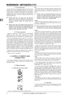
EURORACK UB1222FX-PRO 2.1.4 Pan, mute switch and channel fader Fig. 2.2: The equalizer of the input channels The upper (HIGH) and the lower band (LOW) are shelving filters that increase or decrease all frequencies above or below their cut-off frequency. The cut-off frequencies of the upper and lower band are 12 kHz and 80 Hz respectively. The mid band is configured as a peak filter with a center frequency of 2.5 kHz. Unlike shelving filters, the peak filter processes a frequency range that extends upwards and downwards around its middle frequency. 2.1.3 Aux sends (MON and FX) Fig. 2.3: The AUX SEND controls in the channel strips Aux sends take signals via a control from one or more channels and sum these signals to a so-called bus. This bus signal is sent to an aux send connector and then routed, for example, to an active monitor speaker or an external effects device. The return from an external effects device can then be brought back into the console via the aux return connectors. For situations that require effects processing, the aux sends are usually switched post-fader so that the effects volume in a channel corresponds to the position of the channel fader. If this were not the case, the effects signal of the channel would remain audible even when the fader is turned to zero. When setting up a monitor mix, the aux sends are generally switched to pre-fader; i.e. they operate independently of the position of the channel fader. Both aux sends are mono, are sourced after the equalizer and offer up to +15 dB gain. + If you press the MUTE switch of the respective channel, aux sends and returns (MON and FX) are not being muted. MON In the UB1222FX-PRO, aux send 1 (MON) is wired pre-fader and is thus particularly suitable for setting up monitor mixes. FX The aux send labeled FX is for feeding external effects devices and is thus set up to be post-fader. In the UB1222FX-PRO, the FX send is routed directly to the built-in effects processor. To make sure that the effects processor receives an input signal, you shouldn’t turn this control all the way to the left (-oo). Don’t have the FX MUTE switch pressed, and you should also not have the FX SEND fader pulled down. Fig. 2.4: Channel fader and additional control elements PAN The PAN control determines the position of the channel signal within the stereo image. This control features a constant-power characteristic, which means the signal is always maintained at a constant level, irrespective of position in the stereo panorama. MUTE Use the MUTE switch to mute the channel. This means that the channel signal is no longer present in the main mix. However, the aux sends (MON and FX) remain active. MUTE LED The MUTE LED indicates that the relevant channel is muted. CLIP LED The CLIP LED lights up when the input signal is driven too high. In this case, lower apparent frequency increase on the channel EQ to avoid distortion. For example, lower the mids and the highs somewhat to emphasize the bass. If you don’t wish to change the EQ settings under any circumstances, try lowering the TRIM control somewhat (counterclockwise). If you inserted an external effects processor via the insert connector (e. g. a dynamic processor), then you should also control its output signal level. It should not be higher than its input signal level (0 dB). The channel fader determines the level of the channel signal in the main mix. + Attention: Since the aux path for the effect processor is connected post-fader, the channel fader has to be turned up in order to get this channel’s signal to the effects processor! 2. CONTROL ELEMENTS AND CONNECTORS 7
-
 1
1 -
 2
2 -
 3
3 -
 4
4 -
 5
5 -
 6
6 -
 7
7 -
 8
8 -
 9
9 -
 10
10 -
 11
11 -
 12
12 -
13
-
14
-
15
 |
 |
