Behringer ULTRALINK UL2000B Manual - Page 20
To assure good reception, if possible, install the ULR2000 as high in a rack as possible, so
 |
View all Behringer ULTRALINK UL2000B manuals
Add to My Manuals
Save this manual to your list of manuals |
Page 20 highlights
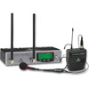
ULTRALINK UL2000B To assure good reception, if possible, install the ULR2000 as high in a rack as possible, so that the antennae protrude above the upper edge of the rack. The ULR2000 requires one height unit (1 HE) for installation in a 19-inch rack. Please assure that there are additional 10 cm (4 inches) of free space in the back for connecting cables. For installation in a rack, use M6 machine screws and nuts. Be sure that there is plenty of space around the unit for cooling and, to avoid overheating, please do not place the ULR2000 on top of power amplifiers or other heat-emitting equipment. If you wish to install more than 2 units in a rack, please make sure that there is enough space between them (fig. 5.1). The lower unit's antennae may not perturb against the upper unit's antennae. Otherwise, they could interfere with one another, causing a decrease in reception quality. Fig. 5.1: Arrangement of multiple ULR2000s when installed on top of each other 20 5. INSTALLATION
-
 1
1 -
2
-
3
-
4
-
5
-
6
-
7
-
8
-
9
-
10
-
11
-
12
-
13
-
14
-
 15
15 -
 16
16 -
 17
17 -
 18
18 -
 19
19 -
 20
20 -
 21
21 -
 22
22 -
 23
23 -
 24
24 -
 25
25 -
26
 |
 |
