Beko HBG60 User Manual - Page 8
Installing your appliance
 |
View all Beko HBG60 manuals
Add to My Manuals
Save this manual to your list of manuals |
Page 8 highlights
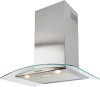
2 Installing your appliance •• Assembly and electrical connections must be carried out by specialized personnel. •• Wear protective gloves before proceeding with the installation. Electrical Connection: •• The appliance has been manufactured as a class II, therefore no earth cable is necessary. The plug must be easily accessible after the installation of the appliance. If the appliance is equipped with power cord without plug, a suitably dimensioned omnipolar switch with 3 mm minimum opening between contacts must be fitted between the appliance and the electricity supply in compliance with the load and current regulations. •• The connection to the mains is carried out as follows: BROWN = L line BLUE = N neutral. •• The minimum distance between the support surfaces of the cooking pots on the cooker top and the lowest part of the cooker hood must be at least 65 cm. If a connection tube composed of two parts is used, the upper part must be placed outside the lower part. Do not connect the cooker hood exhaust to the same conductor used to circulate hot air or for evacuating fumes from other appliances generated by other than an electrical source. Before proceeding with the assembly operations, remove the anti-grease filter(s) (Fig.7) so that the unit is easier to handle. •• In the case of assembly of the appliance in the suction version prepare the hole for evacuation of the air. •• We recommend the use of an air exhaust tube which has the same diameter as the air exhaust outlet hole. If a pipe with a smaller diameter is used, the efficiency of the product may be reduced and its operation may become noisier. Please note: If your version of the appliance has decorative glass before installing the hood, carry out the following steps as shown in figure 4: 1. Remove both the cooker hood body B and the glass panel A from the packaging and place them horizontally on a secure surface. 2. Take the glass panel A and position it above the cooker hood body B. 3. Fix the glass panel securely to the cooker hood body using the 4 sleeves C and 4 screws D as indicated. Fixing to the wall: Drill the holes A respecting the distances indicated (Fig.2). Fix the appliance to the wall and align it in horizontal position to the wall units. When the appliance has been adjusted, definitely fix the hood using the screws A (Fig.5). For the various installations use screws and screw anchors suited to the type of wall (e.g. reinforced concrete, plasterboard, etc.). If the screws and screw anchors are provided with the product, check that they are suitable for the type of wall on which the hood is to be fixed. Fixing the decorative telescopic flue: A WARNING: If your appliance model features the lower connector with a tab, before fixing it in place bend the tab inwards using a pair of pliers, as illustrated in figure 5, step1. 8 / 13 EN Cooker Hood / User Manual
-
 1
1 -
2
-
 3
3 -
 4
4 -
 5
5 -
 6
6 -
 7
7 -
 8
8 -
 9
9 -
 10
10 -
 11
11 -
 12
12 -
 13
13 -
14
-
15
-
16
 |
 |
