Beko HNAG64225S User Manual - Page 10
mm/480-490
 |
View all Beko HNAG64225S manuals
Add to My Manuals
Save this manual to your list of manuals |
Page 10 highlights
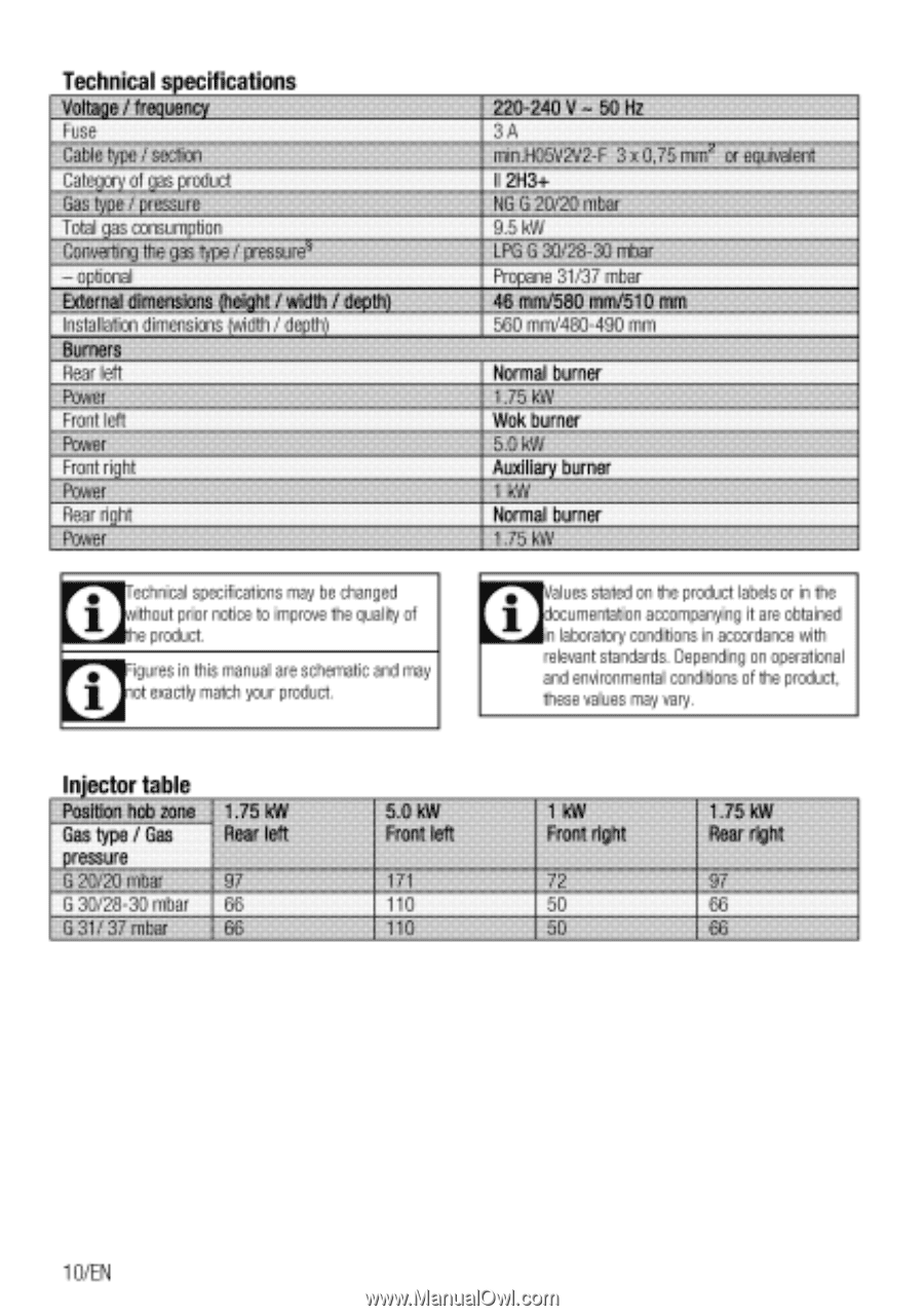
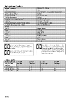
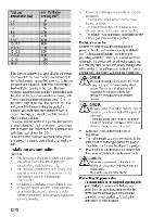
Technical specifications Voltage / frequency Fuse Cable type / section Category of gas product Gas type / pressure Total gas consumption Converting the gas type / prekeilre - optional External dimensions ftelaht / width / depth) Installation dimensions (width / depth) Burners Rear left Power Front left Power Front right Power Rear right Power • ethnical specifications may be changed 1 ithout prior notice to improve the quality of he product. • figures in this manual are schematic and may 1 of exactly match your product. 220-240 V - 50 Hz 3A min HO5V2V2-F 3 x 0,75 mm` or equivalent II 2H3+ NG G 20/20 mbar 9.5 kW LPG G 30/28-30 mbar Propane 31/37 mbar 46 mm/ mm 560 mm/480-490 mm Normal burner 1.75 kW Wok burner 5.0 kW Auxiliary burner 1 kW Normal burner alues stated on the product labels or in the documentation accompanying it are obtained in laboratory conditions in accordance with relevant standards. Depending on operational and environmental conditions of the product, these values may vary. Injector table Position hob zone__ 1.75 kW Gas type / Gas Jim' left pressure G 20/20 mbar G 30/28-30 mbar 66 G 31/ 37 rribarill 5.0 kW Front left 171 110 110 1 kW Front right 72 50 50 1.75 kW Rear right 97 66 66 10/EN
-
 1
1 -
2
-
3
-
4
-
 5
5 -
 6
6 -
 7
7 -
 8
8 -
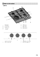 9
9 -
 10
10 -
 11
11 -
 12
12 -
 13
13 -
 14
14 -
 15
15 -
16
-
17
-
18
-
19
-
20
-
21
-
22
-
23
-
24
 |
 |