Beko HNAG64225S User Manual - Page 14
conversion
 |
View all Beko HNAG64225S manuals
Add to My Manuals
Save this manual to your list of manuals |
Page 14 highlights
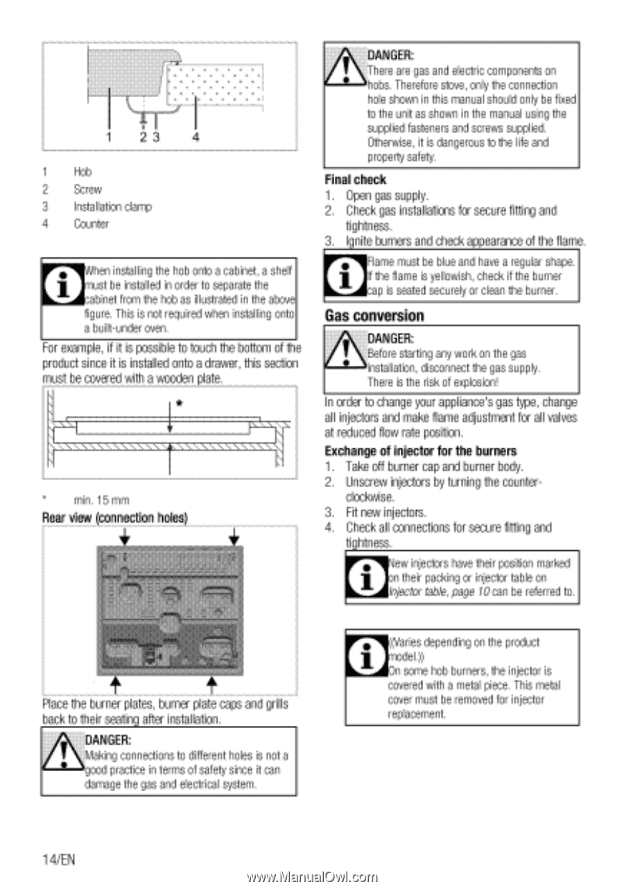
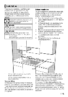
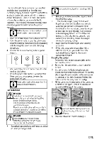
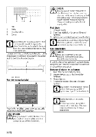
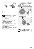
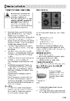
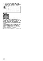
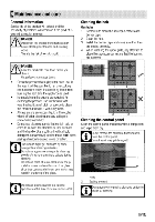
23 4 1 Hob 2 Screw 3 Installation clamp 4 Counter When installing the hob onto a cabinet, a shelf must be installed in order to separate the cabinet from the hob as illustrated in the above figure. This is not required when installing onto a built-under oven. For example, if it is possible to touch the bottom of the product since it is installed onto a drawer, this section must be covered with a wooden plate. min. 15 mm Rear view (connection holes) DANGER: There are gas and electric components on hobs. Therefore stove, only the connection hole shown in this manual should only be fixed to the unit as shown in the manual using the supplied fasteners and screws supplied. Otherwise, it is dangerous to the life and property safety. Final check 1. Open gas supply. 2. Check gas installations for secure fitting and tightness. 3. Ignite burners and check appearance of the flame. Flame must be blue and have a regular shape. If the flame is yellowish, check if the burner asap is seated securely or clean the burner. AGas conversion , DANGER: I Before starting any work on the gas • installation, disconnect the gas supply. There is the risk of explosion! In order to change your appliance's gas type, change all injectors and make flame adjustment for all valves at reduced flow rate position. Exchange of injector for the burners 1. Take off burner cap and burner body. 2. Unscrew injectors by turning the counter- clockwise. 3. Fit new injectors. 4. Check all connections for secure fitting and tightness. New injectors have their position marked their packing or injector table on Injector table, page 10 can be referred to. AiPlace the burner plates, burlier plate caps and grills back to their seating after installation. DANGER: I Making connections to different holes is not a • good practice in terms of safety since it can damage the gas and electrical system. ((Varies depending on the product model.)) On some hob burners, the injector is covered with a metal piece. This metal cover must be removed for injector replacement. 1 4/EN
-
 1
1 -
2
-
3
-
4
-
5
-
6
-
7
-
8
-
 9
9 -
 10
10 -
 11
11 -
 12
12 -
 13
13 -
 14
14 -
 15
15 -
 16
16 -
 17
17 -
 18
18 -
 19
19 -
20
-
21
-
22
-
23
-
24
 |
 |