Biostar I945G-M7 Setup Manual - Page 10
JCFAN1: CPU Fan Header, JSFAN1: System Fan Header - cpu support
 |
View all Biostar I945G-M7 manuals
Add to My Manuals
Save this manual to your list of manuals |
Page 10 highlights
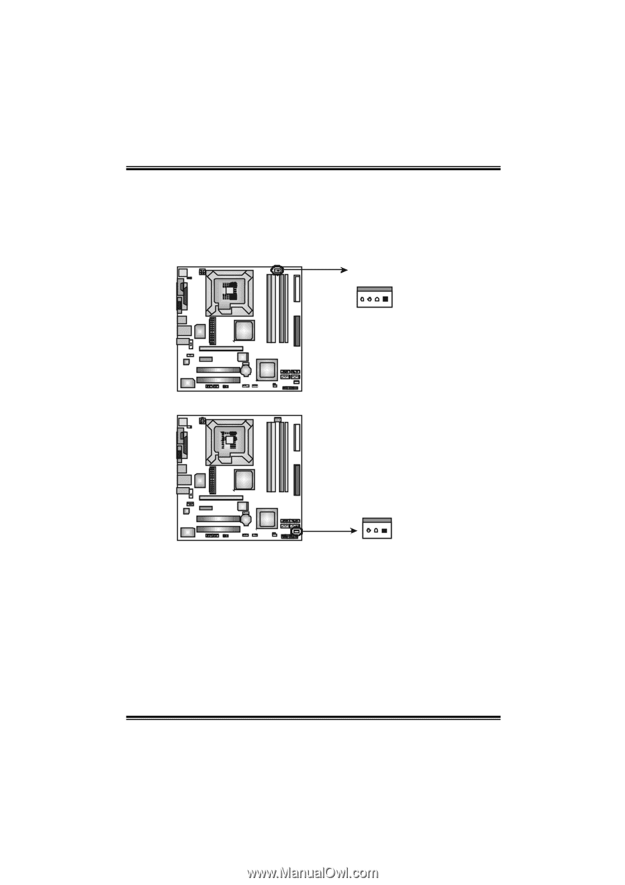
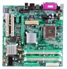
945G-M7 / 945P-M7 2.2 FAN HEADERS These fan headers support cooling-fans built in the computer. The fan cable and connector may be different according to the fan manufacturer. Connect the fan cable to the connector while matching the black wire to pin#1. JC FAN1: C PU Fan Heade r JCFA N1 4 1 Pin 1 2 3 4 Assignment Ground Power FAN RPM rate sense Smart Fan Control JSFAN1: System Fan He ader Pin 1 2 3 JS FA N1 31 Assignment Ground +12V FAN RPM rate sense Note: The JCFAN1 and JSFAN1 res erve s ystem cooling fan with Smart Fan Contr ol utility. It supports 4-pi n and 3-pin head c onnector. When connec ting with wires onto connectors, pleas e note that the red wire is the positi ve and s hould be c onnected to pin#2, and the blac k wire is Ground and s hould be c onnected to GND. 8
-
 1
1 -
2
-
3
-
4
-
 5
5 -
 6
6 -
 7
7 -
 8
8 -
 9
9 -
 10
10 -
 11
11 -
 12
12 -
 13
13 -
 14
14 -
 15
15 -
16
-
17
-
18
-
19
-
20
-
21
-
22
-
23
-
24
-
25
-
26
-
27
-
28
-
29
-
30
-
31
-
32
-
33
-
34
-
35
-
36
-
37
-
38
-
39
-
40
-
41
-
42
-
43
-
44
-
45
-
46
-
47
-
48
-
49
-
50
-
51
-
52
-
53
-
54
-
55
-
56
-
57
-
58
-
59
-
60
-
61
-
62
-
63
-
64
-
65
-
66
-
67
-
68
 |
 |