Biostar IDEQ 200A iDEQ 200A user's manual - Page 19
Jumpers, Headers, Connectors, Slots
 |
View all Biostar IDEQ 200A manuals
Add to My Manuals
Save this manual to your list of manuals |
Page 19 highlights
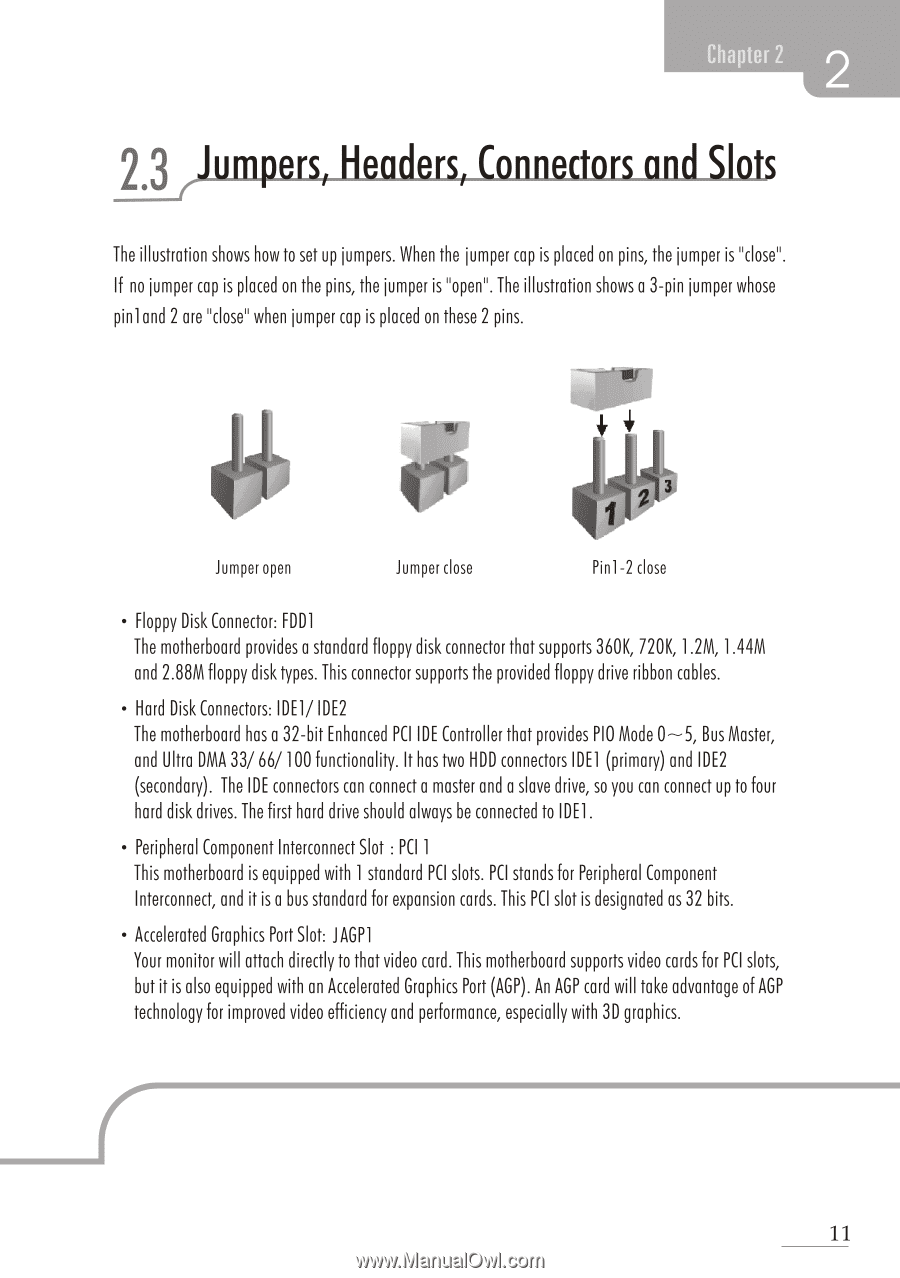
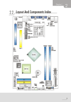
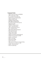
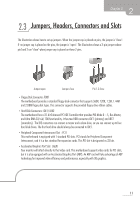
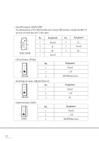
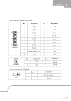
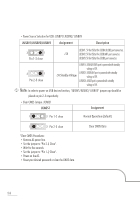
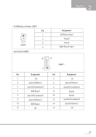
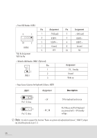
2 Chapter 2 2.3 / Jumpers, Headers, Connectors and Slots The illustration shows how to set up jumpers. When the jumper cop is placed on pins, the jumper is "close". If no jumper cap is placed on the pins, the jumper is "open". The illustration shows a 3-pin jumper whose pinl and 2 are "close" when jumper cap is placed on these 2 pins. Jumper open Jumper close Pinl -2 close • Floppy Disk Connector: FDD1 The motherboard provides a standard floppy disk connector that supports 360K, 720K, 1.2M, 1.44M and 2.88M floppy disk types. This connector supports the provided floppy drive ribbon cables. • Hard Disk Connectors: IDE1/ IDE2 The motherboard has a 32-bit Enhanced PCI IDE Controller that provides PIO Mode 0.5, Bus Master, and Ultra DMA 33/ 66/ 100 functionality. It has two HDD connectors IDE1 (primary) and IDE2 (secondary). The IDE connectors can connect a master and a slave drive, so you can connect up to four hard disk drives. The first hard drive should always be connected to IDEl. • Peripheral Component Interconnect Slot : PCI 1 This motherboard is equipped with 1 standard PCI slots. PCI stands for Peripheral Component Interconnect, and it is a bus standard for expansion cards. This PCI slot is designated as 32 bits. • Accelerated Graphics Port Slot: J AGP1 Your monitor will attach directly to that video card. This motherboard supports video cards for PCI slots, but it is also equipped with an Accelerated Graphics Port (AGP). An AGP card will take advantage of AGP technology for improved video efficiency and performance, especially with 3D graphics. 11
-
 1
1 -
2
-
3
-
4
-
5
-
6
-
7
-
8
-
9
-
10
-
11
-
12
-
13
-
 14
14 -
 15
15 -
 16
16 -
 17
17 -
 18
18 -
 19
19 -
 20
20 -
 21
21 -
 22
22 -
 23
23 -
 24
24 -
25
-
26
-
27
-
28
-
29
-
30
-
31
-
32
-
33
-
34
-
35
-
36
-
37
-
38
-
39
-
40
-
41
-
42
-
43
-
44
-
45
-
46
-
47
-
48
-
49
-
50
-
51
-
52
-
53
-
54
-
55
-
56
 |
 |