Biostar N4SIE-A7 N4SIE-A7 user's manual - Page 17
JSPDIF_OUT/JSPDIF_IN1: Digital Audio-out Connectors, JSPDIF_IN1 is optional., JAUDIO2: Front Panel
 |
View all Biostar N4SIE-A7 manuals
Add to My Manuals
Save this manual to your list of manuals |
Page 17 highlights
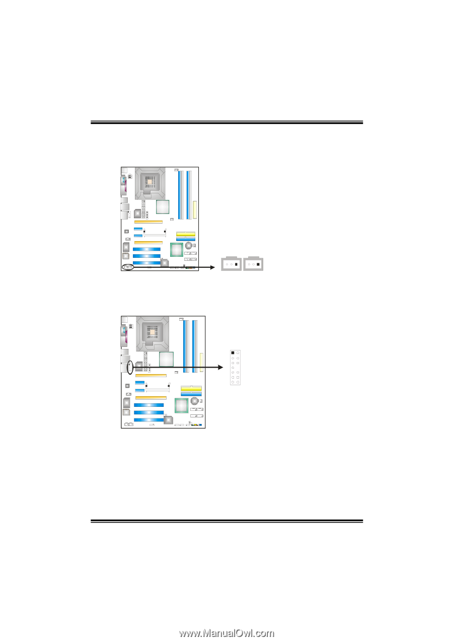
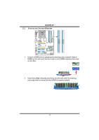
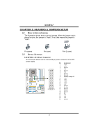
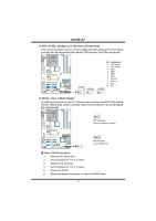
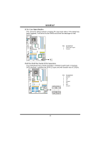
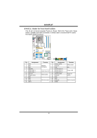
N4SIE-A7 JSPDIF_OUT/JSPDIF_IN1: Digital Audio-out Connectors (JSPDIF_IN1 is optional.) These connectors allow user to connect the PCI bracket SPDIF output or input header. JSPDIF_OUT: Pin Assignment 1 +5V 2 SPDIF OUT 3 Ground JSPDIF_IN1 (optional) JSPDIF_OUT1 JSPDIF_IN1 (optional): Pin Assignment 1 +5V 2 SPDIF IN 3 Ground 31 31 JAUDIO2: Front Panel Audio-out Header This connector will allow user to connect with the front audio out put headers on the PC case. It will disable the output on back panel audio connectors. 12 13 14 Pin Assignment 1 MIC-in/ Stereo MIC-in R 2 Ground 3 Stereo MIC-in L 4 Audio power 5 Right line-out/ Speaker-out Right. 6 Right line-out/ Speaker-out Right 7 Reserved 8 Key 9 Left line-out/ Speaker-out Left 10 Left line-out/ Speaker-out Left 11 Right line-in 12 Right line-in 13 Left line-in 14 Left line-in 15
-
 1
1 -
2
-
3
-
4
-
5
-
6
-
7
-
8
-
9
-
10
-
11
-
 12
12 -
 13
13 -
 14
14 -
 15
15 -
 16
16 -
 17
17 -
 18
18 -
 19
19 -
 20
20 -
 21
21 -
 22
22 -
23
-
24
-
25
-
26
-
27
-
28
-
29
-
30
-
31
-
32
-
33
-
34
-
35
-
36
-
37
-
38
-
39
-
40
-
41
 |
 |