Biostar N4SIE-A7 N4SIE-A7 user's manual - Page 28
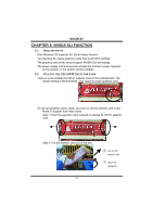
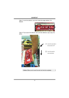
Step 7-1: Remove any of the bracket cover between the two
 |
View all Biostar N4SIE-A7 manuals
Add to My Manuals
Save this manual to your list of manuals |
Page 28 highlights
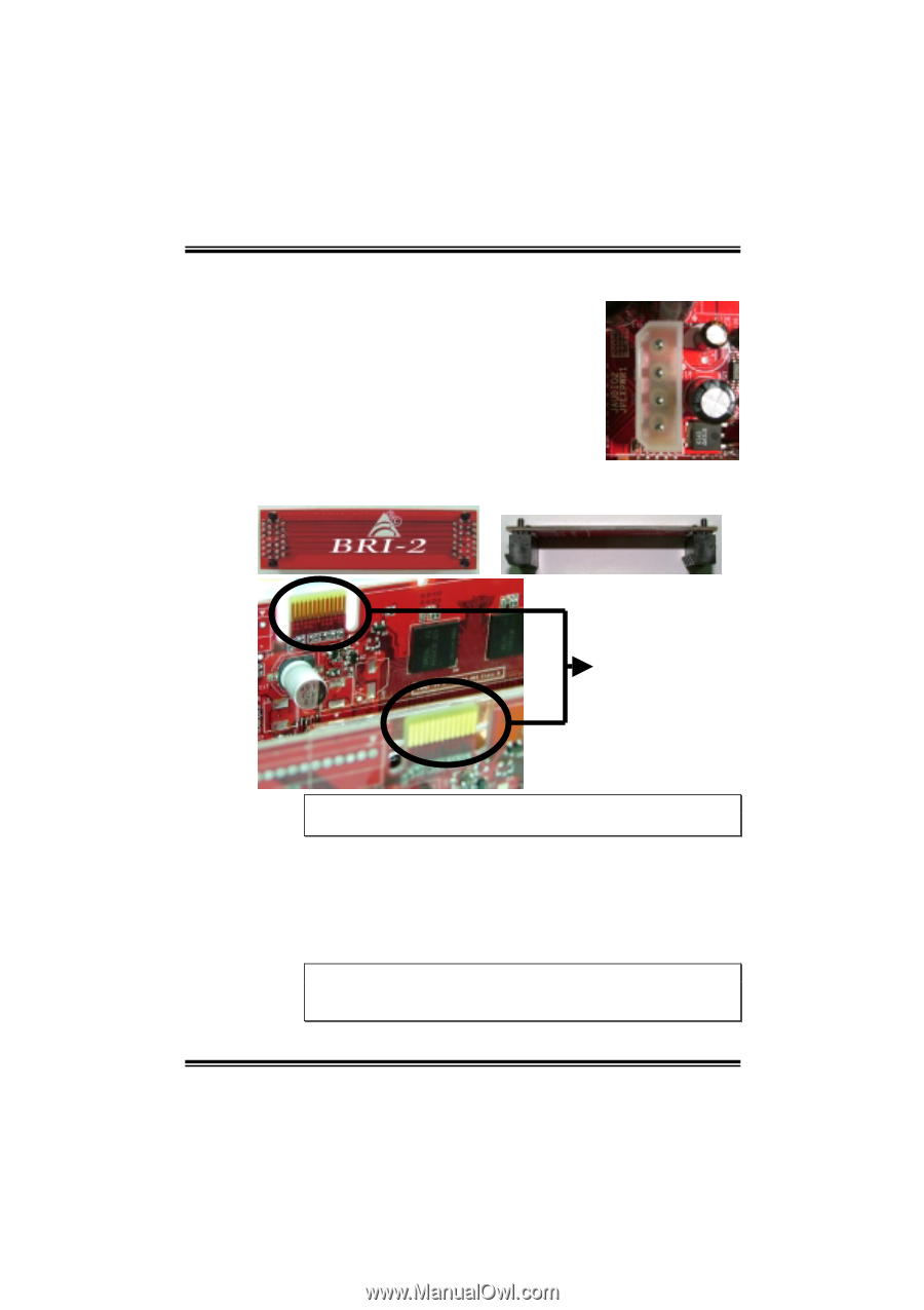
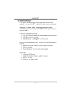
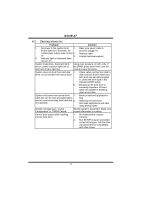
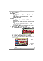
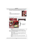
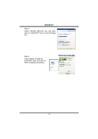
N4SIE-A7 Step 5: Connect a 4-pin ATX power cable to AUX power connector (JAUXPWR1), this will ensure the stabilization of your system. Notice: When under SLI mode, please make sure the power supply is at least 500W (and above). Step 6: Insert the SLI Bridge (BRI-2) connector on the gold-fingers of each graphics card. Gold-fingers on two graphics Notice: Please make good preservation of this bridge for future use. Step 7: To securely fix the connector between two graphics cards, a retention bracket must be installed. Step 7-1: Remove any of the bracket cover between the two graphics cards. Step 7-2: Align and insert the retention bracket into the slot and then fix it with a screw. Notice: Make sure the retention bracket supports the SLI Bridge (BRI-2) firmly. 26
-
 1
1 -
2
-
3
-
4
-
5
-
6
-
7
-
8
-
9
-
10
-
11
-
12
-
13
-
14
-
15
-
16
-
17
-
18
-
19
-
20
-
21
-
22
-
 23
23 -
 24
24 -
 25
25 -
 26
26 -
 27
27 -
 28
28 -
 29
29 -
 30
30 -
 31
31 -
 32
32 -
 33
33 -
34
-
35
-
36
-
37
-
38
-
39
-
40
-
41
 |
 |