Biostar P4TCA PRO P4TCA Pro user's manual
Biostar P4TCA PRO Manual
 |
View all Biostar P4TCA PRO manuals
Add to My Manuals
Save this manual to your list of manuals |
Biostar P4TCA PRO manual content summary:
- Biostar P4TCA PRO | P4TCA Pro user's manual - Page 1
energy and, if not installed and used in accordance with the instructions, may cause harmful interference to radio communications. There is no guarantee vendor's approval in writing. The content of this user's manual is subject to be changed without notice and we will not be responsible for any mistakes - Biostar P4TCA PRO | P4TCA Pro user's manual - Page 2
CCoonntteenntt ENGLISH 1 P4TCA Pro Features 1 Package contents ...3 Layout of P4TCA Pro 4 Component Index ...5 How to set up Jumper 6 CPU Installation ...6 DDR DIMM Modules: DDRA1-2, DDRB1-2 7 Installing DDR Module 8 Serial Raid ...8 Installing Wireless LAN Card 9 Jumpers, Headers, Connectors - Biostar P4TCA PRO | P4TCA Pro user's manual - Page 3
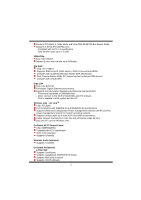
English P4TCA Pro Features A. Hardware CPU Provides Socket-478. Supports the Intel Pentium 4 processor up to 3.06GHz. Front Side Bus at 400/533/800MHz. Supports Hyper-Treading. Chipset North Bridge: Intel 875P South Bridge: Intel ICH5R. Main Memory Supports one or two 64-bit wide DDR data channels - Biostar P4TCA PRO | P4TCA Pro user's manual - Page 4
with transfer up to 400mbps. IDE-Raid Chip: VIA VT6410. Supports RAID Level 0, RAID Level 1, RAID 0+1 Level and JBOD. Complies with Scatter/Gather Bus Master DMA Mechanism. Dual Channel Master Mode PCI supporting four enhanced IDE devices. Complies with ATA/ATAPI7. Giga LAN Chip: Intel 82547EI. Full - Biostar P4TCA PRO | P4TCA Pro user's manual - Page 5
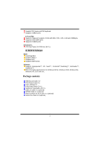
Function. Software Supports Warpspeeder™, 9th Touch™, FLASHER™,Watchdog™, WinFlasher™, StudioFun!™. Offers the highest performance for Windows 98 SE, Windows 2000, Windows Me, Windows XP, SCO UNIX etc. Package contents HDD Round Cable X 2 FDD Round Cable X 1 User's Manual X1 Fully Setup Driver CD - Biostar P4TCA PRO | P4TCA Pro user's manual - Page 6
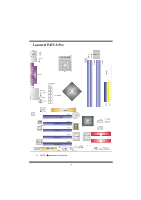
Layout of P4TCA Pro ※ NOTE: ●represents the first pin. 4 - Biostar P4TCA PRO | P4TCA Pro user's manual - Page 7
) F CNR1: Communication Network Riser Slot G JWOL1: Wake On LAN Header H JSPDIF_OUT1: Digital Audio Connector I JUSB2: Front USB Header N JSFAN1: System Fan Header O JPANEL: Front Panel Connector P RAID1-2: Raid Connector Q SATA1-2: Serial ATA Connector R JCL1: Case Open Connector S JCMOS - Biostar P4TCA PRO | P4TCA Pro user's manual - Page 8
"close" when jumper cap is placed on these 2 pins. Jumper open Jumper close Pin1-2 close CPU Installation Step1: Pull the lever sideways away from the socket and then raise the lever up to a 90-degree angle. Step2: Look for the white dot/cut edge. The white dot/cut edge should point - Biostar P4TCA PRO | P4TCA Pro user's manual - Page 9
biostar.com.tw) Supports DDR 333 or DDR 400 unregistered ECC or non-ECC DDR DIMMS. DRAM Access Time: 2.5V Unbuffered/ Registered DDR SDRAM PC1600/ PC2100 Type required. DRAM Type: 128MB/ 256MB/ 512MB/ 1GB DIMM Module (184 pin) Total Memory Size with Unbuffered/ Registered DIMMs DIMM Socket - Biostar P4TCA PRO | P4TCA Pro user's manual - Page 10
Controller' will be presented - select this driver to install. 5. Finish the Windows XP installation and install all necessary drivers. 6. Install the Intel Application Accelerator RAID Edition 3.0 software via the CD-ROM included with your motherboard or after downloading it from the Internet. This - Biostar P4TCA PRO | P4TCA Pro user's manual - Page 11
Card 1. Align the wireless LAN on the slot such that wireless LAN card matches in the slot. Be sure to face the wireless LAN card with its components towards the inner part of the motherboard. 2. Insert the wireless LAN card vertically and firmly into the slot so the wireless card is properly seated - Biostar P4TCA PRO | P4TCA Pro user's manual - Page 12
ATA Connector: JSATA1/JSATA2 The motherboard has a PCI to SATA Controller with 2 channels STAT interface, it satisfy the SATA 1.0 spec and can transfer data with 1.5GHz speed. IDE-Raid Connector: RAID1/2 This connector supports RAID0 or RAID1 or RAID 0+1 configuration through the onboard Parallel - Biostar P4TCA PRO | P4TCA Pro user's manual - Page 13
Front USB Header: JUSB2/3 Pin Assignment Pin Assignment 2 10 1 +5V(fused) 2 +5V(fused) 1 9 3 USBP4- 4 USBP5- 5 USBP4+ 6 USBP5+ JUSB2/3 7 Ground 8 Ground 9 KEY 10 NC Wake On LAN Header: JWOL1 Pin 1 1 2 JWOL1 3 Assignment +5V_SB Ground Wake up 11 - Biostar P4TCA PRO | P4TCA Pro user's manual - Page 14
Power Connectors: JATXPWER1/ JATXPWR2 10 20 PIN Assignment PIN Assignment 1 +3.3V 11 +3.3V 2 +3.3V 12 -12V 3 Ground 13 Ground 4 +5V 14 PS_ON 5 Ground 15 Ground 1 11 JATXPWR1 6 +5V 16 Ground 7 Ground 17 Ground 8 PW_OK 18 -5V 9 +5V_SB 19 +5V 10 +12V 20 +5V - Biostar P4TCA PRO | P4TCA Pro user's manual - Page 15
5V/ 5VSB Selection for USB: JUSBV1/JUSBV3_4 JUSBV1/JUSBV3 Assignment _4 Description 1 3 +5V Pin 1-2 close 5V for JUSB1/2/3 1 3 Pin 2-3 close +5V_SB 5V standby to power on JUSB1/2/3 Clear CMOS Jumper: JCMOS1 JCMOS1 Assignment 1 3 Pin 1-2 Close Normal Operation (default) 1 3 Pin 2-3 - Biostar P4TCA PRO | P4TCA Pro user's manual - Page 16
Game Header: JGAME1 15 1 16 2 JGAME1 Pin Assignment Pin Assignment 1 +5V 2 +5V 3 GP6 4 GP4 5 GP2 6 GP0 7 MIDI-OUTR 8 Ground 9 GP3 10 Ground 11 GP7 12 GP1 13 MIDI-INR 14 GP5 15 NC 16 +5V CD-ROM Audio-In Header: JCDIN1 1 JCDIN1 Pin Assignment 1 Left - Biostar P4TCA PRO | P4TCA Pro user's manual - Page 17
1 AUDIO DJ Connector: JAUDIO_DJ1 5 1 JAUDIO_DJ1 Pin Assignment Pin 1 SMBDATA 2 3 INT_B 4 5 ATX_PWROK Assignment SMBCLK KEY Back Panel Connectors Mouse Parallel 1 3 LAN Line In/ Surround Speaker Out 1 3 Mic In/ Bass&Center Keyboard USB COM1 JKBMS1 JUSB1 JCOM1 COM2 JCOM2 USB - Biostar P4TCA PRO | P4TCA Pro user's manual - Page 18
automatically rebooting the computer and then restart to a speed that is either the original system speed or a suitable one. System Requirement OS Support: Windows 98 SE, Windows Me, Windows 2000, Windows XP DirectX: DirectX 8.1 or above. (The Windows XP operating system includes DirectX 8.1. If you - Biostar P4TCA PRO | P4TCA Pro user's manual - Page 19
Installation 1. Execute the setup execution file, and then the following dialog will pop up. Please click "Next" button and follow the default procedure to install. 2. When you see the following dialog in setup procedure, it means setup is completed. If the "Launch the WarpSpeeder Tray Utility" - Biostar P4TCA PRO | P4TCA Pro user's manual - Page 20
Usage The following figures are just only for reference, the screen printed in this user manual will change according to your motherboard on hand. [WarpSpeeder™] includes 1 tray icon and 5 panels: 1. Tray Icon: Whenever the Tray Icon utility is launched, it will display a little tray icon on the - Biostar P4TCA PRO | P4TCA Pro user's manual - Page 21
This utility is responsible for conveniently invoking [WarpSpeeder™] Utility. You can use the mouse by clicking the left button in order to invoke [WarpSpeeder™] directly from the little tray icon or you can right-click the little tray icon to pop up a popup menu as following figure. The "Launch - Biostar P4TCA PRO | P4TCA Pro user's manual - Page 22
3. Voltage Panel Click the Voltage button in Main Panel, the button will be highlighted and the Voltage Panel will slide out to up as the following figure. In this panel, you can decide to increase CPU core voltage and Memory voltage or not. The default setting is "No". If you want to get the best - Biostar P4TCA PRO | P4TCA Pro user's manual - Page 23
21 - Biostar P4TCA PRO | P4TCA Pro user's manual - Page 24
3MHz button", "-1MHz button", "+1MHz button", and "+3MHz button": provide user the ability to do real-time overclock adjustment. Warning: Manually overclock is potentially dangerous, especially when the overclocking percentage is over 110 %. We strongly recommend you verify every speed you overclock - Biostar P4TCA PRO | P4TCA Pro user's manual - Page 25
hardware default setting or load the verified best and stable frequency according to the Recovery Dialog's setting. Note: Because the testing programs, invoked in Auto-overclock and Verify, include DirectDraw, Direct3D and DirectShow tests, the DirectX 8.1 or newer runtime library is required. And - Biostar P4TCA PRO | P4TCA Pro user's manual - Page 26
5. Hardware Monitor Panel Click the Hardware Monitor button in Main Panel, the button will be highlighted and the Hardware Monitor panel will slide out to left as the following figure. In this panel, you can get the real-time status information of your system. The information will be refreshed every - Biostar P4TCA PRO | P4TCA Pro user's manual - Page 27
Note: Because the overclock, overvoltage, and hardware monitor features are controlled by several separate chipset, [ WarpSpeeder™ ] divide these features to separate panels. If one chipset is not built in on board, the correlative button in Main panel will be disabled, but will not interfere other - Biostar P4TCA PRO | P4TCA Pro user's manual - Page 28
Trouble Shooting PROBABLE SOLUTION No power to the system at all Power light don't * Make sure power cable is securely plugged in illuminate, fan inside power supply does not turn on. Indicator light on keyboard does not turn on * Replace cable * Contact technical support program and select - Biostar P4TCA PRO | P4TCA Pro user's manual - Page 29
04/10/2003 27
-
 1
1 -
 2
2 -
 3
3 -
 4
4 -
 5
5 -
 6
6 -
 7
7 -
8
-
9
-
10
-
11
-
12
-
13
-
14
-
15
-
16
-
17
-
18
-
19
-
20
-
21
-
22
-
23
-
24
-
25
-
26
-
27
-
28
-
29
 |
 |

P
P
4
4
T
T
C
C
A
A
P
P
r
r
o
o
i
FCC Information and Copyright
This equipment has been tested and found to comply with the limits of a
Class B digital device, pursuant to Part 15 of the FCC Rules. These limits
are designed to provide reasonable protection against harmful
interference in a residential installation. This equipment generates, uses
and can radiate radio frequency energy and, if not installed and used in
accordance with the instructions, may cause harmful interference to radio
communications. There is no guarantee that interference will not occur in
a particular installation.
The vendor makes no representations or warranties with respect to the
contents here of and specially disclaims any implied
warranties
of
merchantability or fitness for any purpose. Further the vendor reserves
the right to revise this publication and to make changes to the contents
here of without obligation to notify any party beforehand.
Duplication of this publication, in part or in whole, is not allowed without
first obtaining the vendor’s approval in writing.
The content of this user’s manual is subject to be changed without notice
and we will not be responsible for any mistakes found in this user’s
manual. All the brand and product names are trademarks of their
respective companies.