Biostar P4TDH Setup Manual - Page 13
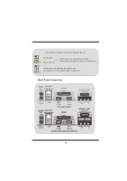
Back Panel Connectors
 |
View all Biostar P4TDH manuals
Add to My Manuals
Save this manual to your list of manuals |
Page 13 highlights
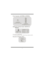
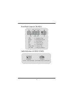
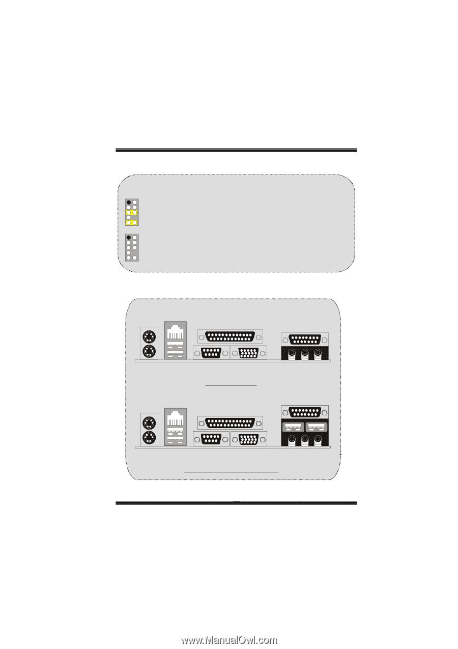
Front Panel Audio Connector/ Jumper Block 12 Pin 5 and 6 Audio line out signals are routed 9 10 ==> to the back panel audio line out connector. Pin 9 and 10 12 Audio line out and mic in signals are available for front panel audio connectors. 9 10 Back Panel Connectors JKBMS1 RJ45USB1 PS/2 LAN(Optional) Mouse JPRNT1 Parallel JGAME1_USB1 Game Port PS/2 Keyboard USB JKBMS1 RJ45USB1 PS/2 LAN(Optional) Mouse COM1 VGA1 JCOM1 JVGA1 (Normal Mode) JPRNT1 Parallel Speaker Line In Mic Out In JGAME1_USB1 Game Port/ USB Ports (optional) PS/2 Keyboard USB COM1 VGA1 JCOM1 JVGA1 Speaker Line In Mic Out In (Add USB Game Port Mode) 10
-
 1
1 -
2
-
3
-
4
-
5
-
6
-
7
-
 8
8 -
 9
9 -
 10
10 -
 11
11 -
 12
12 -
 13
13 -
 14
14 -
 15
15 -
 16
16 -
 17
17 -
 18
18 -
19
-
20
-
21
-
22
-
23
-
24
-
25
-
26
-
27
-
28
-
29
-
30
-
31
-
32
-
33
-
34
-
35
-
36
-
37
-
38
-
39
-
40
-
41
-
42
-
43
-
44
-
45
-
46
-
47
-
48
-
49
-
50
-
51
-
52
-
53
-
54
-
55
-
56
-
57
-
58
-
59
-
60
 |
 |
10
Back Panel Connectors
PS/2
Keyboard
PS/2
Mouse
COM1
Parallel
Game Port/
USB Ports (optional)
JPRNT1
JGAME1_USB1
JCOM1
JKBMS1
USB
LAN(Optional)
RJ45USB1
COM1
Speaker
Out
Line In
Mic
In
JVGA1
VGA1
PS/2
Keyboard
PS/2
Mouse
COM1
Parallel
Game Port/
USB Ports (optional)
JPRNT1
JGAME1_USB1
JCOM1
JKBMS1
USB
LAN(Optional)
RJ45USB1
COM1
Speaker
Out
Line In
Mic
In
JVGA1
VGA1
PS/2
Keyboard
PS/2
Mouse
COM1
Parallel
Game Port
JPRNT1
JGAME1_USB1
JCOM1
JKBMS1
USB
LAN(Optional)
RJ45USB1
COM1
Speaker
Out
Line In
Mic
In
JVGA1
VGA1
(Normal Mode)
(Add USB Game Port Mode)
1
2
Front Panel Audio Connector/ Jumper Block
9
10
Audio line out signals are routed
to the back panel audio line out connector.
Pin 5 and 6
==>
Pin 9 and 10
1
2
9
10
Audio line out and mic in signals are
available for front panel audio connectors.