Biostar P4TDH Setup Manual - Page 8
Jumpers, Headers, Connectors & Slots - motherboards
 |
View all Biostar P4TDH manuals
Add to My Manuals
Save this manual to your list of manuals |
Page 8 highlights
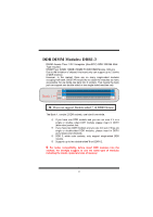
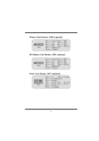
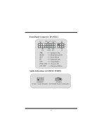
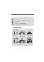
Jumpers, Headers, Connectors & Slots Hard Disk Connectors: IDE1/ IDE2/ (IDE3=>optional) The motherboard has a 32-bit Enhanced PCI IDE Controller that provides PIO Mode 0~4, Bus Master, and Ultra DMA / 33/ 66/ 100 functionality. It has three HDD connectors IDE1 (primary), IDE2 (secondary) and IDE3 (optional). The IDE connectors can connect a master and a slave drive, so you can connect up to four hard disk drives. The first hard drive should always be connected to IDE1. Serial ATA Connector: (JSATA1/ JSATA2=>optional) The motherboard has a PCI to SATA Controller with 2 channels S-ATA interface, it satisfy the SATA 1.0 spec and can transfer data up to 1.5GHz speed. Floppy Disk Connector: FDD1 The motherboard provides a standard floppy disk connector that supports 360K, 720K, 1.2M, 1.44M and 2.88M floppy disk types. This connector supports the provided floppy drive ribbon cables. Accelerated Graphics Port Slot: AGP1 Your monitor will attach directly to that video card. This motherboard supports video cards for PCI slots, but it is also equipped with an Accelerated Graphics Port (AGP/ only 1.5V and 4X AGP card can be supported). An AGP card will take advantage of AGP technology for improved video efficiency and performance, especially with 3D graphics. Communication Network Riser Slot: CNR1 The CNR specification is an open Industry Standard Architecture, and it defines a hardware scalable riser card interface, which supports audio, network and modem only. Peripheral Component Interconnect Slots: PCI1-5 This motherboard is equipped with 5 standard PCI slots. PCI stands for Peripheral Component Interconnect, and it is a bus standard for expansion cards, which has, supplanted the older ISA bus standard in most ports. This PCI slot is designated as 32 bits. 5
-
 1
1 -
2
-
 3
3 -
 4
4 -
 5
5 -
 6
6 -
 7
7 -
 8
8 -
 9
9 -
 10
10 -
 11
11 -
 12
12 -
 13
13 -
14
-
15
-
16
-
17
-
18
-
19
-
20
-
21
-
22
-
23
-
24
-
25
-
26
-
27
-
28
-
29
-
30
-
31
-
32
-
33
-
34
-
35
-
36
-
37
-
38
-
39
-
40
-
41
-
42
-
43
-
44
-
45
-
46
-
47
-
48
-
49
-
50
-
51
-
52
-
53
-
54
-
55
-
56
-
57
-
58
-
59
-
60
 |
 |