Biostar TFORCE 6100 AM2 Setup Manual - Page 21
Power Source Selection Headers for Keyboard/Mouse: JKBMSV1, Header to adjust Memory Voltage: JDDR_II - overclock
 |
View all Biostar TFORCE 6100 AM2 manuals
Add to My Manuals
Save this manual to your list of manuals |
Page 21 highlights
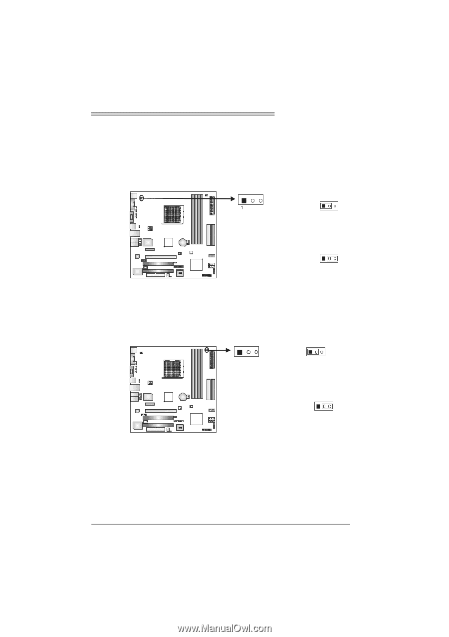
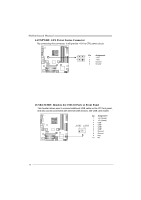
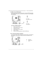
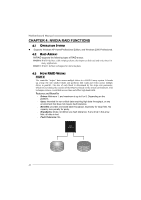
TForce 6100 AM2 Power Source Selection Headers for Keyboard/Mouse: JKBMSV1 Pin 1-2 Close: JKBMSV1: +5V for PS/2 keyboard and mouse。 Pin 2-3 Close: JKBMSV1: PS/2 keyboard and mouse are powered with +5V standby voltage. 13 Pin 1-2 close 13 Pin 2-3 close Header to adjust Memory Voltage: JDDR_II>2.2V When adjusting Memory Voltage, please place the jumper to pin2-3 Closed. The Default setting is Pin 1-2 Closed. 13 1 Pin 1-2 Close: Memory Voltage controlled by BIOS (default). 13 Pin 2-3 Close: Memory voltage Overclocking Note: 1. When "JDDR_II>2.2V" jumper cap is placed on Pin 1-2, memory voltage can be manually adjusted under CMOS setup. 2. When "JDDR_II>2.2V" jumper cap is placed on Pin 2-3, memory voltage will be fixed at 2.2V automatically, and can't be adjusted under COMS setup. Before setting memory voltage overclocking, please ensure that your DDRII memory modules are able to support 2.2V. (Consulting your DDR supplier) 19
-
 1
1 -
2
-
3
-
4
-
5
-
6
-
7
-
8
-
9
-
10
-
11
-
12
-
13
-
14
-
15
-
 16
16 -
 17
17 -
 18
18 -
 19
19 -
 20
20 -
 21
21 -
 22
22 -
 23
23 -
 24
24 -
 25
25 -
 26
26 -
27
-
28
-
29
-
30
-
31
-
32
-
33
-
34
-
35
-
36
-
37
-
38
-
39
-
40
-
41
-
42
-
43
-
44
-
45
-
46
-
47
-
48
-
49
-
50
-
51
-
52
-
53
-
54
-
55
-
56
-
57
-
58
-
59
-
60
-
61
-
62
-
63
-
64
-
65
-
66
-
67
-
68
-
69
-
70
-
71
-
72
-
73
-
74
-
75
-
76
-
77
-
78
-
79
-
80
-
81
-
82
-
83
-
84
-
85
-
86
-
87
-
88
-
89
-
90
-
91
-
92
-
93
-
94
-
95
-
96
-
97
-
98
-
99
-
100
-
101
-
102
-
103
-
104
-
105
 |
 |