Biostar U8568 PRO U8568 Pro user's manual - Page 16
Front Panel Connector: JPANEL1
 |
View all Biostar U8568 PRO manuals
Add to My Manuals
Save this manual to your list of manuals |
Page 16 highlights
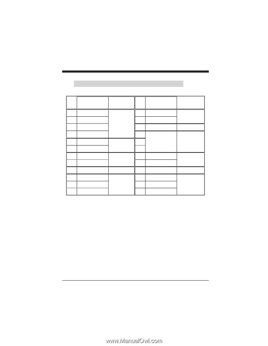
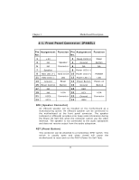
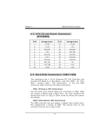
4-1. Front Panel Connector: JPANEL1 Pin Assignment Function Pin Assignment Function No. No. 1 +5V 2 Sleep Control Sleep 3 NA Speaker 4 Ground Button 5 NA Connector 6 NA NA 7 Speaker 8 Power LED (+) 9 HDD LED (+) Hard Drive 10 Power LED (+) POWER 11 HDD LED (-) LED 12 Power LED (-) LED 13 Ground Reset 14 Power Button Power-on 15 Reset Control Button 16 Ground Button 17 NA 18 KEY 19 NA IrDA 20 KEY IrDA 21 VCC5 Connector 22 Ground Connector 23 IRTX 24 IRRX SPK (Speaker Connector) An offboard speaker can be installed on the motherboard as a manufacturing option. An offboard speaker can be connected to the motherboard at the front panel connector. The speaker (onboard or offboard) provides error beep code information during the Power On Self-Test when the computer cannot use the video interface. The speaker is not connected to the audio subsystem and does not receive output from the audio subsystem. RST (Reset Button) This connector can be attached to a momentary SPST switch. This switch is usually open and when closed will cause the motherboard to reset and run the POST (Power On Self Test).
-
 1
1 -
2
-
3
-
4
-
5
-
6
-
7
-
8
-
9
-
10
-
 11
11 -
 12
12 -
 13
13 -
 14
14 -
 15
15 -
 16
16 -
 17
17 -
 18
18 -
 19
19 -
 20
20 -
 21
21 -
22
-
23
-
24
-
25
-
26
-
27
-
28
-
29
-
30
-
31
-
32
-
33
-
34
-
35
-
36
-
37
-
38
-
39
-
40
-
41
-
42
-
43
-
44
-
45
-
46
-
47
-
48
 |
 |