Biostar U8568 PRO U8568 Pro user's manual - Page 31
Serial and Parallel Interface Ports
 |
View all Biostar U8568 PRO manuals
Add to My Manuals
Save this manual to your list of manuals |
Page 31 highlights
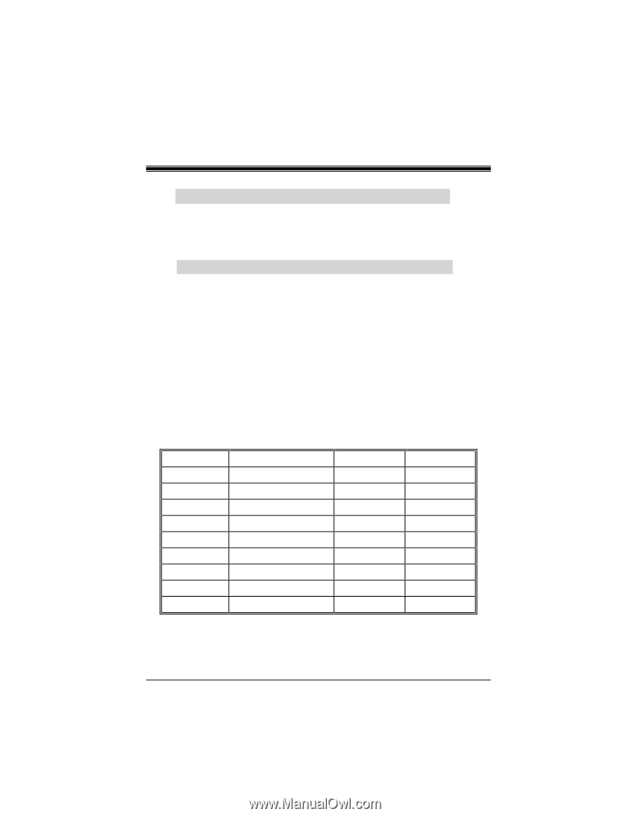
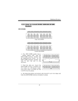
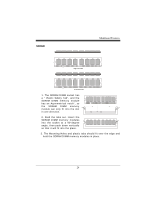
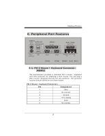
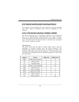
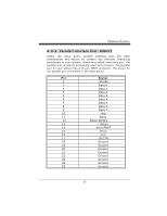
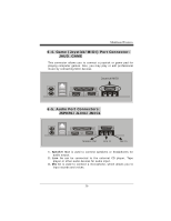
6-3. Serial and Parallel Interface Ports This system comes equipped with one serial port and one parallel port. Both types of interface ports will be explained in this chapter. 6-3-1. The Serial Interface: JCOM1/ JCOM2 The serial interface port is sometimes referred to as an RS-232 port or an asynchronous communication port. Mice, printers, modems and other peripheral devices can be connected to a serial port. The serial port can also be used to connect your computer with another computer system. Connectivity The serial ports can be used in many ways, and it may be necessary to become familiar with the pinout diagram. The following chart gives you the function of each pin on the 9-pin connector and some of the 25-pin connector. This information can be used when configuring certain software programs to work with the serial ports. Signal DCD RX TX DTR GND DSR RTS CTS RI Name Data Carrier Detect Receive Data Transmit Data Data Terminal Ready Signal Ground Data Set Ready Request to Send Clear to Send Ring Indicator DB9 PIN 1 2 3 4 5 6 7 8 9 DB25 PIN 8 3 2 20 7 6 4 5 22
-
 1
1 -
2
-
3
-
4
-
5
-
6
-
7
-
8
-
9
-
10
-
11
-
12
-
13
-
14
-
15
-
16
-
17
-
18
-
19
-
20
-
21
-
22
-
23
-
24
-
25
-
 26
26 -
 27
27 -
 28
28 -
 29
29 -
 30
30 -
 31
31 -
 32
32 -
 33
33 -
 34
34 -
 35
35 -
 36
36 -
37
-
38
-
39
-
40
-
41
-
42
-
43
-
44
-
45
-
46
-
47
-
48
 |
 |