Black & Decker BDECS300C Instruction Manual - Page 8
Assembly/Adjustment Set-Up
 |
View all Black & Decker BDECS300C manuals
Add to My Manuals
Save this manual to your list of manuals |
Page 8 highlights
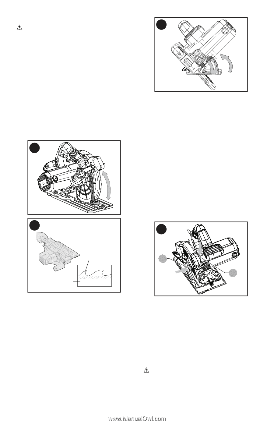
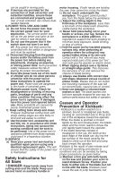
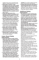
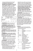
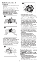
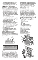
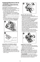
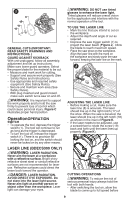
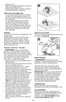
Assembly/Adjustment Set-Up WARNING: Always unplug saw from power supply before any of the following operations. ADJUSTING THE DEPTH OF CUT The depth of cut should be set according to the thickness of the workpiece. • Loosen the depth adjustment lever (12) to unlock the saw shoe (4). • Move the saw shoe into the desired position (Figure E). The corresponding depth of cut can be read from the depth scale (13). • Tighten the lever to lock the saw shoe in place. • Set depth adjustment of saw such that one tooth of the blade projects below the workpiece as shown in Figure F. E F G INSTALLING THE BLADE • Keep the spindle lock button (16) depressed and rotate the blade until the spindle lock engages. • Loosen and remove the blade retaining screw (11) by turning the hex wrench (15) counterclockwise (Figure H). • Remove the outer washer (10). • Place the saw blade (5) onto the spindle shaft, making sure that the arrow on the blade points in the same direction as the arrow on the upper gaurd of the tool. • Fit the outer washer on the spindle with the larger flat surface against the blade. • Insert the blade retaining screw into the hole in the spindle. • Securely tighten the blade retaining screw by turning hex wrench clockwise to tighten the blade retaining screw. H Tip of tooth 11 16 Surface of wood ADJUSTING THE BEVEL ANGLE This tool can be set to bevel angles between 0° and 45°. • Loosen the locking knob (9) to unlock the saw shoe. • Move the saw shoe (4) into the desired position (Figure G). The corresponding bevel angle can be read from the scale (14). • Tighten the locking knob to lock the saw shoe in place. REMOVING THE BLADE • Loosen and remove the blade retaining screw (11) by turning it counterclockwise using the hex wrench (15). • Remove the outer washer (10). • Remove the saw blade (5). NOTICE: Never engage the spindle lock while the saw is running. Never turn the saw on while the spindle lock is engaged. Severe damage to the saw may result. WARNING: To reduce the risk of serious personal injury, read, understand and follow all important safety warnings and instructions prior to using tool. 8
-
 1
1 -
2
-
 3
3 -
 4
4 -
 5
5 -
 6
6 -
 7
7 -
 8
8 -
 9
9 -
 10
10 -
 11
11 -
 12
12 -
 13
13 -
14
-
15
-
16
-
17
-
18
-
19
-
20
-
21
-
22
-
23
-
24
-
25
-
26
-
27
-
28
-
29
-
30
-
31
-
32
-
33
-
34
-
35
-
36
-
37
-
38
 |
 |