Bosch 1803EVS Operating Instructions - Page 9
Operating Instructions
 |
UPC - 000346302431
View all Bosch 1803EVS manuals
Add to My Manuals
Save this manual to your list of manuals |
Page 9 highlights
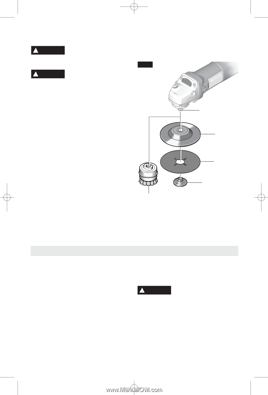
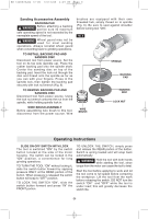
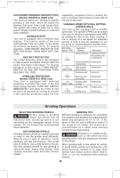
BM 1609929J64 12-05 12/12/05 4:07 PM Page 9 Sanding Accessories Assembly BACKING PAD ! WARNING Before attaching a backing pad be sure its maximum safe operating speed is not exceeded by the nameplate speed of the tool. ! WARNING Wheel guard may not be used for most sanding operations. Always reinstall wheel guard when converting back to grinding operations. TO INSTALL BACKING PAD AND SANDING DISC Disconnect tool from power source. Set the tool on its top side (spindle up). Place the rubber backing pad onto the spindle shaft. Center the sanding disc on top of the backing pad. Insert the lock nut through the disc and thread onto the spindle as far as you can with your fingers. Press in the spindle lock, then tighten the backing pad securely with lock nut wrench (Fig. 6). TO REMOVE BACKING PAD AND SANDING DISC Disconnect tool from power source. Using the lock nut wrench unscrew the nut from the spindle, while holding spindle lock in. WIRE BRUSH ASSEMBLY Before assembling wire brush to this tool, disconnect from the power source. Wire brushes are equipped with their own threaded hub, simply thread on to spindle (Fig. 6). Be sure to seat against shoulder before turning tool "ON". FIG. 6 WIRE BRUSH SPINDLE BACKING PAD SANDING DISC LOCK NUT Operating Instructions SLIDE ON-OFF SWITCH WITH LOCK The tool is switched "ON" by the switch button located at the side of the motor housing. The switch can be locked in the "ON" position, a convenience for long grinding operations. TO TURN THE TOOL "ON" without locking it, slide the switch button forward by applying pressure ONLY at the REAR portion of the button. When pressure is released the switch button will snap to "OFF" position. TO LOCK THE SWITCH "ON", slide the switch button forward and press "IN" the FRONT portion. TO UNLOCK THE SWITCH, simply press and release the REAR portion of the button. Switch is spring loaded and will snap back automatically. ! WARNING Hold the tool with both hands while starting the tool, since torque from the motor can cause the tool to twist. Start the tool before applying to work and let the tool come to full speed before contacting the workpiece. Lift the tool from the work before releasing the switch. DO NOT turn the switch "ON" and "OFF" while the tool is under load; this will greatly decrease the switch life. -9-
-
 1
1 -
2
-
3
-
 4
4 -
 5
5 -
 6
6 -
 7
7 -
 8
8 -
 9
9 -
 10
10 -
 11
11 -
 12
12 -
 13
13 -
 14
14 -
15
-
16
-
17
-
18
-
19
-
20
-
21
-
22
-
23
-
24
-
25
-
26
-
27
-
28
-
29
-
30
-
31
-
32
-
33
-
34
-
35
-
36
-
37
-
38
 |
 |