Bosch HEI7282U Installation Instructions - Page 15
Wire Stripping, Attaching Wire to Lug, Table 3: Appropriate Torque Levels for Aluminum or Copper
 |
UPC - 825225844365
View all Bosch HEI7282U manuals
Add to My Manuals
Save this manual to your list of manuals |
Page 15 highlights
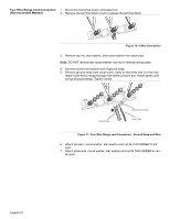
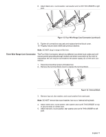
8. Strip 3/8 (9.53 mm) inches of insulation from the end of the wire. 3/8 " Figure 16: Wire Stripping 9. Insert the insulated grounding wire into the lug below the terminal block. 10. Insert stripped end of white wire into the center lug. Secure the clamping- screw. lug clamping screw wire Figure 17: Attaching Wire to Lug 11. Insert stripped end of red wire into the left lug. Secure clamping screw. 12. Insert black wire into the right lug. Secure clamping screw. Tighten each clamping screw with the appropriate torque (see table). Table 3: Appropriate Torque Levels for Aluminum or Copper Wire Gauge 6 8 Torque (in./lbs.) 35 25 Torque (Nm) 3.95 2.82 13. Properly secure flexible conduit at knockout on angle and at supply side junction box. The wiring is now complete. green ground screw black wire red wire white wire green ground wire Figure 18: Completed Four Wire Flexible Conduit Connection English 13
-
 1
1 -
2
-
3
-
4
-
5
-
6
-
7
-
8
-
9
-
 10
10 -
 11
11 -
 12
12 -
 13
13 -
 14
14 -
 15
15 -
 16
16 -
 17
17 -
 18
18 -
 19
19 -
 20
20 -
21
-
22
-
23
-
24
-
25
-
26
-
27
-
28
-
29
-
30
-
31
-
32
-
33
-
34
-
35
-
36
-
37
-
38
-
39
-
40
-
41
-
42
-
43
-
44
-
45
-
46
-
47
-
48
-
49
-
50
-
51
-
52
-
53
-
54
-
55
-
56
 |
 |
