Bosch WTMC3321US Use & Care Manual (all languages) - Page 7
Exhaust, connection - electric dryer
 |
UPC - 825225844761
View all Bosch WTMC3321US manuals
Add to My Manuals
Save this manual to your list of manuals |
Page 7 highlights
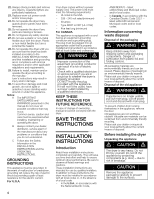
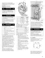
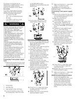
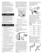
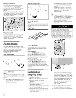
Grounding instruction This appliance must be grounded. In the event of a malfunction or breakdown, grounding will reduce the risk of electric shock by providing a path of least resistance for the electric current. For Canada the dryer comes with a cord which has an equipment grounding conductor and a grounding plug. The plug must be plugged into an appropriate outlet which has been properly installed and grounded in accordance with all local regulations and ordinances. d WARNING d Improper connection of the equipment grounding conductor may result in electric shock. Have the appliance checked by a qualified electrician or service technician if you are in doubt as to whether the dryer has been properly grounded. Exhaust air connection d WARNING d 1. To reduce the risk of fire, this dryer MUST BE EXHAUSTED OUTDOORS. 2. To reduce the risk of fire, do not use the ductwork longer than recommended. 3. DO NOT use a plastic or nonĆmetal duct with this dryer. 4. DO NOT use a duct smaller than 4 inches in diameter. 5. DO NOT use exhaust hoods with magnetic latches. 6. DO NOT exhaust the dryer into a chimney, furnace cold air duct, attic, crawl space, or any other ductwork used for venting. 7. DO NOT install a flexible duct in an enclosed wall, ceiling or floor. 8. DO NOT crush or kink the duct. 9. Do clean and inspect the exhaust system on a regular basis; at least once a year. 10. The exhaust duct must terminate in a manner to prevent back drafts or entry of birds or other wildlife. The Bosch dryers are intended to be vented outdoors. To prevent buildĆup of moisture and accumulation of lint indoors, as well as to maintain maximum drying efficiency, it is recommended that the dryer is vented outdoors. Exhaust air outlet on the dryer The dryer is delivered with an exhaust air outlet on the rear of the appliance. To take account of the spatial requirements and an existing exhaust air system, the following connection options are possible for the exhaust air outlet: - on right side of the appliance, - on the underside of the appliance. 2 1 3 1 ć Exhaust air outlet on the rear of the appliance (standard) 2 ć Exhaust air outlet on the side (optional) 3 ć Exhaust air outlet on the underside of the appliance (optional) Special exhaust air connections must be obtained from your dealer or part supplier for either connection type (see page 8). - Side exhaust kit - Bottom exhaust kit A qualified technician should change the exhaust air outlet to the optional connection location. Ductwork To ensure optimum performance, the ducting system of the dryer should be as short as possible with a minimum number of elbows. Your dryer will work best when the venting system has as few air flow restrictions as possible. Exhaust ducting which is longer than recommended may extend drying time, cause lint to accumulate and affect dryer performance and dryer lifeĆtime. FourĆinch (approx. 100 mm) diameter ducting should be used. Use either rigid metal or flexible metal ducting material. DO NOT use plastic or nonĆmetal duct with this dryer. DO NOT assemble the ductwork with screws or fasteners that extend into the duct. They will serve as an accumulation point for lint. Joints should be secured with aluminum tape. All joints should be tight to avoid leaks. The male end of each duct section must point away from the dryer. Whether connecting to an existing venting system or a new venting system, make sure that all ducting is clean and free of lint. The maximum permitted length for both rigid and flexible metal duct is shown in the table below. Number of Rigid Duct 90° Turns or Elbows Flexible Duct 0 66 ft. 45 ft. (2011 cm) (1372 cm) 1 56 ft. 36 ft. (1707 cm) (1097 cm) 2 48 ft. 29 ft. (1463 cm) (884 cm) 3 39 ft. 22 ft. (1189 cm) (671 cm) 4 30 ft. (914 cm) 16 ft. (488 cm) Note: Side and bottom exhaust installations have a 90° turn inside the dryer. To determine maximum exhaust length, add one 90° turn to the chart. More than two 90° turns are not recommended. For best performance, separate all turns by at least 4 ft. of straight duct, including distance between last turn and exhaust hood. 7
-
 1
1 -
 2
2 -
 3
3 -
 4
4 -
 5
5 -
 6
6 -
 7
7 -
 8
8 -
 9
9 -
 10
10 -
 11
11 -
 12
12 -
13
-
14
-
15
-
16
-
17
-
18
-
19
-
20
-
21
-
22
-
23
-
24
-
25
-
26
-
27
-
28
-
29
-
30
-
31
-
32
-
33
-
34
-
35
-
36
-
37
-
38
-
39
-
40
-
41
-
42
-
43
-
44
-
45
-
46
-
47
-
48
-
49
-
50
-
51
-
52
-
53
-
54
-
55
-
56
-
57
-
58
-
59
-
60
-
61
-
62
-
63
-
64
 |
 |
