Bosch WTMC3321US Use & Care Manual (all languages) - Page 8
Accessories, Installation - door reversal kit
 |
UPC - 825225844761
View all Bosch WTMC3321US manuals
Add to My Manuals
Save this manual to your list of manuals |
Page 8 highlights
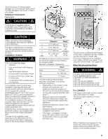
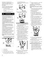
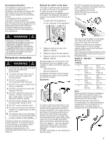
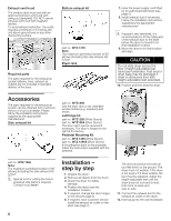
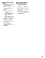
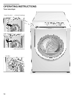
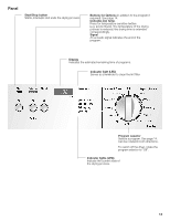
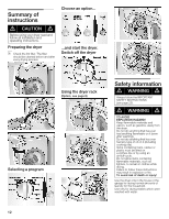
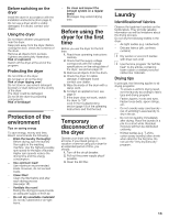
Exhaust vent hood The exhaust duct must end with an approved exhaust vent hood with swing out damper(s). DO NOT use an exhaust vent hood with magnetic latches. To avoid exhaust restriction, the outlet must be a minimum of 12 inches (30 cm) above ground level or any other obstructing surface. Required parts The parts required for the exhaust air system (elbows, lines, exhaust air outlets) are not included in standard delivery of the dryer. Bottom exhaust kit part no. WTZ 1270 Note: The maximum permitted number of 90° elbows (including this side exhaust kit) is four! Dryer rack 7. Have the power supply cord fitted by an authorized technician (see page 5). 8. Install exhaust duct if necessary. Follow the installation instructions supplied by the appropriate manufacturer! i If space is very restricted, it is recommended to fit the initial parts of the exhaust duct to the dryer before the dryer is moved to its final installation location. 9. Move the dryer to its final location and align. CAUTION Do not slide dryer across the floor if heightĆadjustable feet have been extended. Feet and/or dryer base may be damaged if dryer is slid across floor with heightĆadjustable feet extended. 10. Position and then level the dryer. Accessories The parts required for the exhaust air system can be obtained from customer service or your local dealer. Please follow the installation instructions supplied by the appropriate manufacturer! Side exhaust kit part no. WTZ1290 Use the dryer rack to dry washable woolen textiles (e.g. sweaters) and shoes. Left hinge kit part no. WTZ1260 (White Dryers) part no. WTZ126S (Silver Dryers) The door catch can be reversed if necessary. The door is hinged on the right at the factory. Pedestal Mounting Kit part no. WTZ 1295 (White Dryers) part no. WTZ 1295S (Silver Dryers) If mounting the dryer on the pedestal follow the instructions supplied with the pedestal. part no. WTZ 1265 Note: The maximum permitted number of 90° elbows (including this side exhaust kit) is four! i Special tool for cutting the hole in prepared side panel is required. Contact local dealer! 8 Installation ć step by step 1. Unpack the dryer. 2. Remove all objects from the drum. 3. Check the dryer for visible damage. 4. Position the dryer near the installation location. 5. If required, change the door hinges to the left (see page 5). 6. If required, have customer service install the exhaust air outlet on the dryer (see page 7). The dryer should be level with all four feet firmly on the ground. The dryer must not wobble. If the dryer is not level or if it does wobble, the feet must be adjusted. Adjust the heightĆadjustable feet until the dryer does not rock and is level, both frontĆtoĆback and sideĆtoĆside. 11. Connect the exhaust duct to the exhaust air outlet on the dryer. 12. Insert plug into the wall receptacle.
-
 1
1 -
2
-
 3
3 -
 4
4 -
 5
5 -
 6
6 -
 7
7 -
 8
8 -
 9
9 -
 10
10 -
 11
11 -
 12
12 -
 13
13 -
14
-
15
-
16
-
17
-
18
-
19
-
20
-
21
-
22
-
23
-
24
-
25
-
26
-
27
-
28
-
29
-
30
-
31
-
32
-
33
-
34
-
35
-
36
-
37
-
38
-
39
-
40
-
41
-
42
-
43
-
44
-
45
-
46
-
47
-
48
-
49
-
50
-
51
-
52
-
53
-
54
-
55
-
56
-
57
-
58
-
59
-
60
-
61
-
62
-
63
-
64
 |
 |
