Boss Audio 508UAB User Manual - Page 5
Installation Cont.
 |
View all Boss Audio 508UAB manuals
Add to My Manuals
Save this manual to your list of manuals |
Page 5 highlights
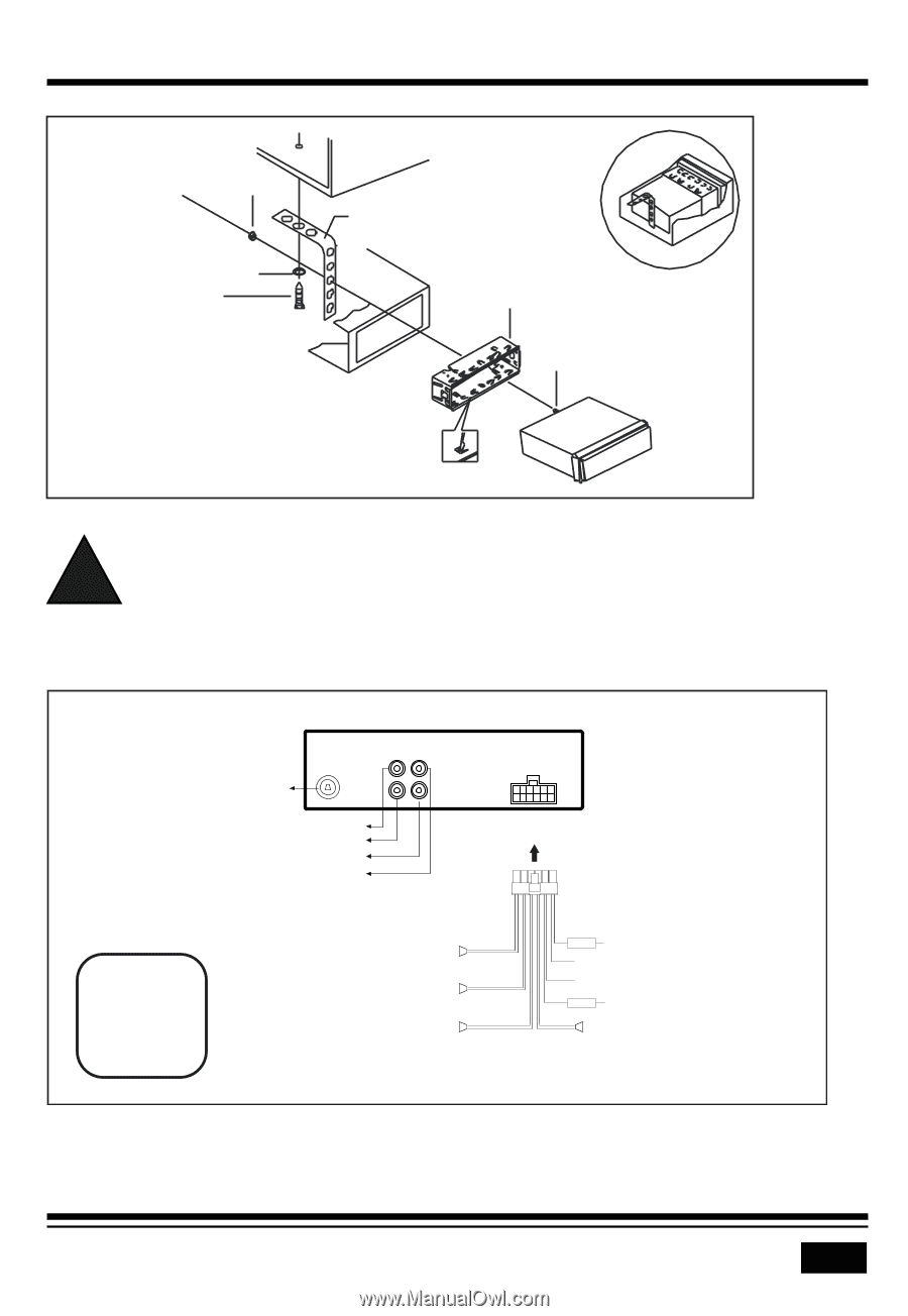
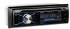
INSTALLATION (CONT.) INSTALLATION DIAGRAM HEX NUT PLAIN WASHER TAPPING SCREW DASH BOARD METAL MOUNTING STRAP CONSOLE MOUNTING SLEEVE HEX BOLT - Only use speakers with 4 ohms impedance. ! - Do not attach the control panel to the chassis before wiring is complete. - The maximum current of the auto antenna is 200mA. Wiring Connections WIRING DIAGRAM Radio Antenna Socket White: Front Left CH RCA Output Red: Front Right CH RCA Output Red: Rear Right CH RCA Output White: Rear Left CH RCA Output CAUTION +12V DC NEGATIVE GROUND Purple + Rear Right Speaker Purple/Black - Fuse 15A Power B+ ( Yellow) GND (Black) Front Right Speaker Gray + Gray/Black - ANT(Blue) Fuse 0.5A ACC (Red) Front Left Speaker White + Green + Rear Left Speaker White/Black - Green/Black - 3
-
 1
1 -
 2
2 -
 3
3 -
 4
4 -
 5
5 -
 6
6 -
 7
7 -
 8
8 -
 9
9 -
 10
10 -
 11
11 -
12
-
13
-
14
-
15
-
16
 |
 |