Boss Audio 628BCK 609UAB_EN_UM.PDF - Page 5
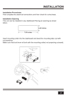
Installationcont.
 |
View all Boss Audio 628BCK manuals
Add to My Manuals
Save this manual to your list of manuals |
Page 5 highlights
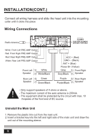
INSTALLATION(CONT.) Connect all wiring harness and slide the head unit into the mounting collar until it clicks into place. Wiring Connections Radio Antenna F-L R-L ANT F-R R-R White: Front Left PRE-AMP Output Red: Front Right PRE-AMP Output Red: Rear Right PRE-AMP Output White: Rear Left PRE-AMP Output Front Left Speaker Rear Left Speaker White White/Black Green Green/Black 10 ACC + (Red) GND - (Black) ANT + (Blue) Power B+ (Yellow) Gray Gray/Black Front Right Speaker Purple Purple/Black Rear Right Speaker - Only support speakers of 4 ohms or above. ! - The maximum current of the auto antenna is 200mA. - The equipment shall be protected by the circuit with max. 10 Amperes of the front end of DC source. Uninstall the Main Unit 1. Remove the plastic trim out from the main unit. 2. Insert a bracket key into the left and right side of the main unit and draw the unit out of the mounting sleeve. 3
-
 1
1 -
 2
2 -
 3
3 -
 4
4 -
 5
5 -
 6
6 -
 7
7 -
 8
8 -
 9
9 -
 10
10 -
 11
11 -
12
-
13
-
14
 |
 |
