Brother International LK3-B430 Service Manual - Page 12
oeeese
 |
View all Brother International LK3-B430 manuals
Add to My Manuals
Save this manual to your list of manuals |
Page 12 highlights
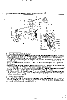
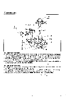
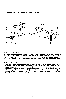
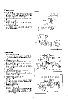
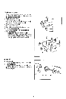
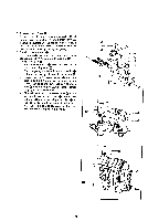
0 00 0 0 0 , [] NEEDLE BAR I. Needle bar 0 Remove oil cap 0, loosen screw 0, pull needle bar -O 0 upward of the arm, and remove needle bar clamp together with slide block 0. 0 2. Remove screw 0 (left-handed) and then needle bar 0. 3. Needle bar crank • 0 0 Remove cap 0. loosen screw ID, and remove needle bar crank 0. Q 4. Thread take-up lever Q, ®. Loosen screw pull out stud ®. thread take-up lever and remove 00 0- • 4D LE THREADING I. Main tension assembly 0 Loosen screw 0. and remove main tension assembly 0, exercising care not to drop the pin out of it. 2. Sub-tension assembly Loosen screw 0.and remove sub-tension assembly also exercising care not to drop the pin out ofit. 3. Thread take-up lever Remove two screws Q and 0, and then thread take-up lever O. 4. Guide stud 0 Remove it by turning it with a screwdriver. ®, 5. Tension release bar plate Remove two screws (1) and washers and then tension relase bar plate 0. Ei POWER WORK CLAMP LIFTER I. Power pulley With the machine at the stop position, remove screw 0 and washer 0, and then power pulley O. 2. Drive lever spring Remove it from pin O. 3. Power cam 0 (I) Remove stop ring 0. (2) Remove stop ring and washer 0, and then ®, • power cam together with drive lever (D. Also remove washer 0, spring washer and washer ®. 0 ®m0 0 -0 • : 0 -its Tr- r e oeeese O®0 09 • 9 1 0 0 -10-
-
 1
1 -
2
-
3
-
4
-
5
-
6
-
 7
7 -
 8
8 -
 9
9 -
 10
10 -
 11
11 -
 12
12 -
 13
13 -
 14
14 -
 15
15 -
 16
16 -
 17
17 -
18
-
19
-
20
-
21
-
22
-
23
-
24
-
25
-
26
-
27
-
28
-
29
-
30
-
31
-
32
-
33
-
34
-
35
-
36
-
37
-
38
-
39
-
40
-
41
-
42
-
43
-
44
-
45
 |
 |
