Brother International LK3-B430 Service Manual - Page 33
THREAD, TENTION, TENSION, RELEASE, Operating, state, operating, 1.0tra
 |
View all Brother International LK3-B430 manuals
Add to My Manuals
Save this manual to your list of manuals |
Page 33 highlights
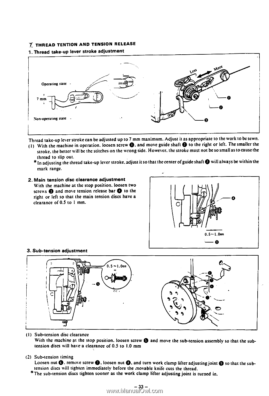
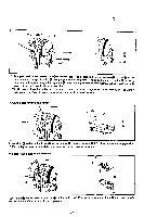
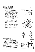
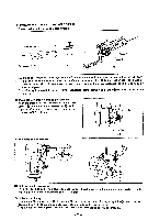
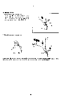
T THREAD TENTION AND TENSION RELEASE 1. Thread take-up lever stroke adjustment Operating state - 7 mm Non-operating state Thread take-up lever stroke can be adjusted up to 7 mm maximum. Adjust it as appropriate to the work to be sewn. (1) With the machine in operation. loosen screw O. and move guide shaft 0 to the right or left. The smaller the stroke. the better will be the stitches on the wrong side. However. the stroke must not be so small as to cause the thread to slip out. * In adjusting the thread take-up lever stroke.adjust it so that the center ofguide shaft 0 will always be within the mark range. 2. Main tension disc clearance adjustment With the machine at the stop position. loosen two screws 0 and move tension release bar 0 to the right or left so that the main tension discs have a clearance of 0.5 to 1 mm. 3. Sub-tension adjustment 0.5 --1.0tra 0.5-1. 0ffn .--- 0 rr • o< O ( I ) Sub-tension disc clearance With the machine at the stop position. loosen screw 0 and move the sub-tension assembly so that the subtension discs will have a clearance of 0.5 to 1.0 mm (21 Sub-tension timing Loosen nut G. remove screw 0. loosen nut 0. and turn work clamp lifter adjusting joint 0 so that the sub- tension discs will tighten immediately before the movable knife cuts the thread. * The sub-tension discs tighten sooner as the work clamp lifter adjusting joint is turned in. - 33 -
-
 1
1 -
2
-
3
-
4
-
5
-
6
-
7
-
8
-
9
-
10
-
11
-
12
-
13
-
14
-
15
-
16
-
17
-
18
-
19
-
20
-
21
-
22
-
23
-
24
-
25
-
26
-
27
-
 28
28 -
 29
29 -
 30
30 -
 31
31 -
 32
32 -
 33
33 -
 34
34 -
 35
35 -
 36
36 -
 37
37 -
 38
38 -
39
-
40
-
41
-
42
-
43
-
44
-
45
 |
 |