Brother International LK3-B430 Service Manual - Page 31
Brother International LK3-B430 Manual
 |
View all Brother International LK3-B430 manuals
Add to My Manuals
Save this manual to your list of manuals |
Page 31 highlights
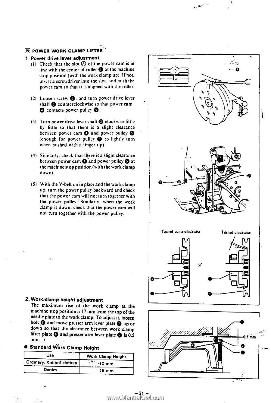
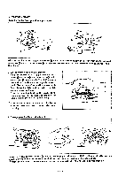
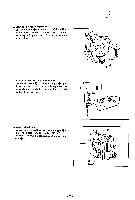
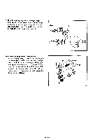
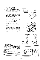
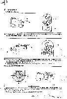
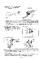
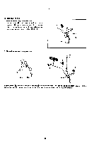
SH POWER WORK CLAMP LIFTER • 1. Power drive lever adjustment (I) Check that the slot 0 of the power cam is in line with the center of roller 0 at the machine stop position (with the work clamp up). If not. insert a screwdriver into the slot, and push the power cam so that it is aligned with the roller. (2) Loosen screw 0. and turn power drive lever shaft Q counterclockwise so that power cam 0 contacts power pulley 0. 13) Turn power drive lever shaft 0 clockwise little by little so that there is a slight clearance between power cam 0 and power pulley 0 (enough for power pulley 0 to lightly turn when pushed with a finger tip). (4) Similarly, check that tiere is a slight clearance between power cam 0 and power pulley 0 at the machine stop position (with the work clamp down). (5) With the V-belt on in place and the work clamp up. turn the power pulley backward and check that the power cam will not turn together with the power Similarly. when the work clamp is down. check that the power cam will not turn together with the power pulley. -0 I N lI 0 0 0 0 Turned conterclockwise Turned clockwise 2. Workvlamp height adjustment The maximum rise of the work clamp at the machine stop position is l7 mm from the top of the needle plate to the work clamp. To adjust it, loosen bolt 10 and move presser arm lever plate 0 up or down so that the clearance between work clamp lifter plate and presser arm lever plate 0 is 0.5 mm. • 0 • Standard Work Clamp Height Use Ordinary, Knitted clothes Denim Work Clamp Height ' \lc .10 mm 15 mm t{ -31 - 0 0 0.5ram 0
-
 1
1 -
2
-
3
-
4
-
5
-
6
-
7
-
8
-
9
-
10
-
11
-
12
-
13
-
14
-
15
-
16
-
17
-
18
-
19
-
20
-
21
-
22
-
23
-
24
-
25
-
 26
26 -
 27
27 -
 28
28 -
 29
29 -
 30
30 -
 31
31 -
 32
32 -
 33
33 -
 34
34 -
 35
35 -
 36
36 -
37
-
38
-
39
-
40
-
41
-
42
-
43
-
44
-
45
 |
 |