Brother International MP-21C Service Manual - Page 35
Main PCB, Data Reception, Control Panel
 |
View all Brother International MP-21C manuals
Add to My Manuals
Save this manual to your list of manuals |
Page 35 highlights
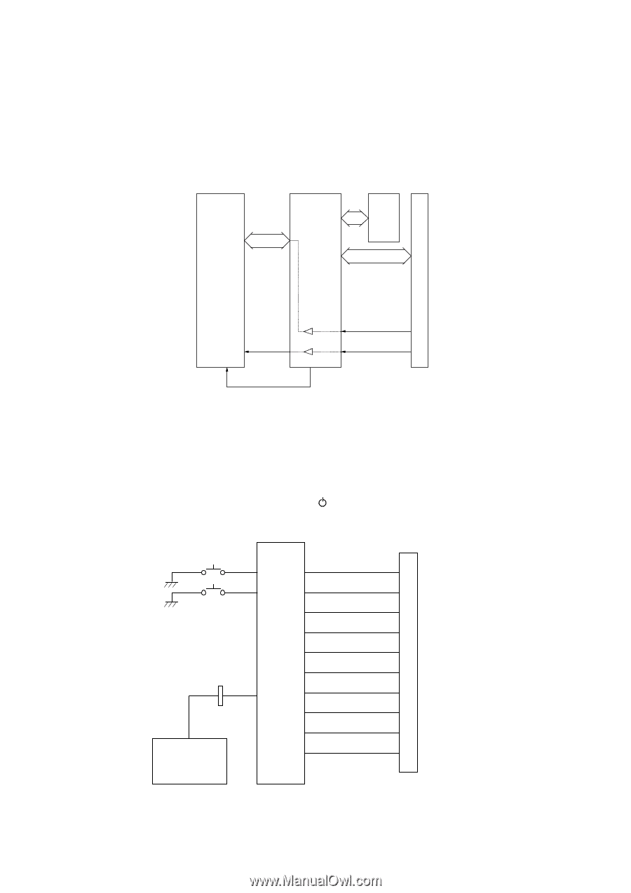
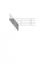
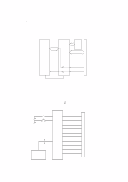
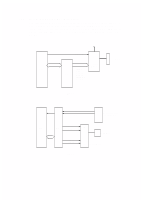
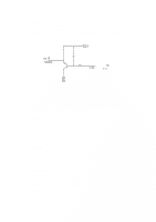
2.3 2.3.1 Main PCB Data Reception IEEE1284 bi-directional nibble mode is supported. The data reception operation is performed by the gate array. The CINT-N signal from the gate array indicates the reception of data to the CPU and control data is processed by the CPU. The printing data is transmitted directly to the memory without being transmitted to the CPU. #4 #7 #8 P8 SRAM Parallel I/F connector CPU G/A IPINT-N 19 SELECT IN-N 18 INPUTPRIME-N 2.3.2 CINT-N Fig. 2.4 Control Panel The control panel controls two switch signal inputs and four LEDs. Two out of four LEDs correspond to each of the ink cartridges. The cover switch is contained in the switch panel. When this switch is OFF, the cover is open and printing is disabled. However, operations associated with cartridge replacement with the cover open are allowed. SW 1 on the Main PCB functions as the (On/Off) button and stops all the operations and turns off the LEDs, but does not turn the power off. P7 ONLINE / Power SW Purge SW CPU P2 MHP Sensor Maintenance unit 5 COVER SW 11 LED POWER 10 LED ALARM 9 LED INKBC 8 LED INKMY Fig. 2.5 II-5
-
 1
1 -
2
-
3
-
4
-
5
-
6
-
7
-
8
-
9
-
10
-
11
-
12
-
13
-
14
-
15
-
16
-
17
-
18
-
19
-
20
-
21
-
22
-
23
-
24
-
25
-
26
-
27
-
28
-
29
-
 30
30 -
 31
31 -
 32
32 -
 33
33 -
 34
34 -
 35
35 -
 36
36 -
 37
37 -
 38
38 -
 39
39 -
 40
40 -
41
-
42
-
43
-
44
-
45
-
46
-
47
-
48
-
49
-
50
-
51
-
52
-
53
-
54
-
55
-
56
-
57
-
58
-
59
-
60
-
61
-
62
-
63
-
64
-
65
-
66
-
67
-
68
-
69
-
70
-
71
-
72
-
73
-
74
-
75
-
76
-
77
-
78
-
79
-
80
-
81
-
82
-
83
-
84
-
85
-
86
-
87
-
88
-
89
-
90
-
91
-
92
-
93
-
94
-
95
-
96
-
97
-
98
-
99
-
100
-
101
-
102
-
103
-
104
-
105
-
106
-
107
-
108
-
109
-
110
-
111
-
112
-
113
-
114
-
115
-
116
-
117
-
118
-
119
-
120
-
121
-
122
-
123
-
124
-
125
-
126
-
127
-
128
-
129
-
130
-
131
-
132
-
133
-
134
-
135
-
136
-
137
-
138
-
139
-
140
-
141
-
142
-
143
-
144
-
145
-
146
-
147
-
148
-
149
-
150
-
151
-
152
-
153
-
154
-
155
-
156
-
157
-
158
-
159
-
160
-
161
-
162
-
163
-
164
-
165
-
166
-
167
-
168
-
169
-
170
-
171
-
172
-
173
-
174
-
175
-
176
-
177
-
178
-
179
-
180
-
181
-
182
-
183
-
184
-
185
-
186
-
187
-
188
-
189
-
190
-
191
-
192
-
193
-
194
-
195
-
196
-
197
-
198
-
199
-
200
-
201
-
202
-
203
-
204
-
205
-
206
-
207
-
208
-
209
-
210
-
211
-
212
-
213
-
214
-
215
-
216
-
217
-
218
-
219
-
220
-
221
-
222
-
223
-
224
-
225
-
226
-
227
-
228
-
229
-
230
-
231
-
232
-
233
 |
 |