Brother International MP-21C Service Manual - Page 67
Main PCB ASSY, Power Supply PCB ASSY, <Disassembly>
 |
View all Brother International MP-21C manuals
Add to My Manuals
Save this manual to your list of manuals |
Page 67 highlights
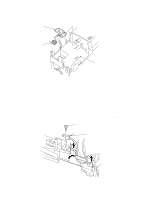
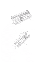
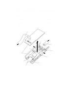
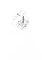
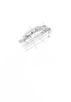
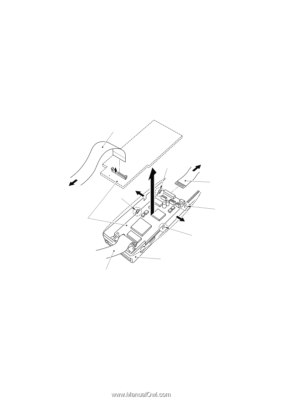
4.6 Main PCB ASSY, Power Supply PCB ASSY Note: After replacing Main PCB ASSY, adjustment is need by using the Service software tool. (1) Remove the Power supply FFC cable (which is connecting the Main PCB ASSY and Power supply PCB ASSY) from the connector on the Main PCB ASSY. (2) Remove the Main PCB ASSY from the Bottom cover by releasing the four hooks. (3) Release the lock of the Head FFC cable connector (which is connecting the Main PCB ASSY and Head PCB ASSY), then remove it from the connector on the Main PCB ASSY. Head FFC Head PCB ASSY Main PCB ASSY Hook Hook Power supply PCB ASSY Power supply FFC Hook Hook Head FFC Bottom cover Fig. 3.18 III-14
-
 1
1 -
2
-
3
-
4
-
5
-
6
-
7
-
8
-
9
-
10
-
11
-
12
-
13
-
14
-
15
-
16
-
17
-
18
-
19
-
20
-
21
-
22
-
23
-
24
-
25
-
26
-
27
-
28
-
29
-
30
-
31
-
32
-
33
-
34
-
35
-
36
-
37
-
38
-
39
-
40
-
41
-
42
-
43
-
44
-
45
-
46
-
47
-
48
-
49
-
50
-
51
-
52
-
53
-
54
-
55
-
56
-
57
-
58
-
59
-
60
-
61
-
 62
62 -
 63
63 -
 64
64 -
 65
65 -
 66
66 -
 67
67 -
 68
68 -
 69
69 -
 70
70 -
 71
71 -
 72
72 -
73
-
74
-
75
-
76
-
77
-
78
-
79
-
80
-
81
-
82
-
83
-
84
-
85
-
86
-
87
-
88
-
89
-
90
-
91
-
92
-
93
-
94
-
95
-
96
-
97
-
98
-
99
-
100
-
101
-
102
-
103
-
104
-
105
-
106
-
107
-
108
-
109
-
110
-
111
-
112
-
113
-
114
-
115
-
116
-
117
-
118
-
119
-
120
-
121
-
122
-
123
-
124
-
125
-
126
-
127
-
128
-
129
-
130
-
131
-
132
-
133
-
134
-
135
-
136
-
137
-
138
-
139
-
140
-
141
-
142
-
143
-
144
-
145
-
146
-
147
-
148
-
149
-
150
-
151
-
152
-
153
-
154
-
155
-
156
-
157
-
158
-
159
-
160
-
161
-
162
-
163
-
164
-
165
-
166
-
167
-
168
-
169
-
170
-
171
-
172
-
173
-
174
-
175
-
176
-
177
-
178
-
179
-
180
-
181
-
182
-
183
-
184
-
185
-
186
-
187
-
188
-
189
-
190
-
191
-
192
-
193
-
194
-
195
-
196
-
197
-
198
-
199
-
200
-
201
-
202
-
203
-
204
-
205
-
206
-
207
-
208
-
209
-
210
-
211
-
212
-
213
-
214
-
215
-
216
-
217
-
218
-
219
-
220
-
221
-
222
-
223
-
224
-
225
-
226
-
227
-
228
-
229
-
230
-
231
-
232
-
233
 |
 |
III-14
4.6
Main PCB ASSY, Power Supply PCB ASSY
Note:
After replacing Main PCB ASSY, adjustment is need by using the
Service software tool.
<Disassembly>
(1)
Remove the Power supply FFC cable (which is connecting the Main PCB ASSY
and Power supply PCB ASSY) from the connector on the Main PCB ASSY.
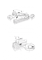
(2)
Remove the Main PCB ASSY from the Bottom cover by releasing the four hooks.
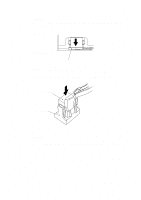
(3)
Release the lock of the Head FFC cable connector (which is connecting the Main
PCB ASSY and Head PCB ASSY), then remove it from the connector on the Main
PCB ASSY.
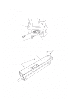
Fig. 3.18
Main PCB ASSY
Hook
Hook
Hook
Hook
Head PCB ASSY
Head FFC
Head FFC
Power supply FFC
Power supply PCB ASSY
Bottom cover