Carvin MX640 Instruction Manual - Page 9
Arvin
 |
View all Carvin MX640 manuals
Add to My Manuals
Save this manual to your list of manuals |
Page 9 highlights
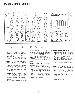
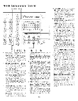
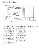
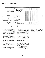
MX640 Rear Connections cD, a, CALMON- To prevent ehacbc shock do not defeat he solely goad he paw cad Do not remove the cover. No user- serviatalote pans inside. WARNING - To pre.ent he or shock.Ima-cl d,not em:ose to rarer moistre. Do not hstal a wrong fuse yak*. DANGER- To prevent a tre hazard. prow* adequale ,entatoM ARVIN HHHHHHHHHHH 1155 Indsstial Ave., Esconzido CA 92029 Tel 619-747-1710 O O 0 ON OFF FUSE 20 VAC:5 AMPS/250V 240 VAC: 2.5 AMPS/250V want USA e Select Mode by MAIN/MONITOR Sw Pg 2-2 SPEAKER OUTPUTS HIGH CURRENT xuR map* MX64O MX640 Mode Amplifier MAIN MON 3 (NOT USEDI GROLNO t.) 2 SIGNAL (a) A Speaker Mono Monitor B Speaker Mono Monitor 20320owatn/Mn Irrp. 4 each 120.240 VAC 5383Hz 560VA FUSE,SA@ IZOVI 25A @240V sbw blcw A SPEAKER 4 Ohms Min B SPEAKER 4 Ohms Min PROVIDE ADEQUATE VENTILATION IT MINIMUM CLEARANCE) 1. AC LINE CORD - The MX640 employs a heavy duty removable grounded AC cord and should only be plugged into a grounded "3 prong" power outlet. If a grounded outlet is not available, the amp should not be used. For safety, no attempt should ever be made to defeat the ground pin of the AC line cord. cord receptacle) and turn it over to the proper voltage as seen on the holder reading right side up k,102voz)-this automatically switches the voltage and the fuse to the proper voltage and fuse value. Be sure to change the fuse value (listed on rear panel) as you change the voltage setting. 6. COOLING - To prevent the PROTECT LED from coming on, be sure the rear heatsink fins have plenty of fresh air. Never lay the unit on its back blocking air. 2. AC LINE FUSE - The MX640 fuse is built into the AC receptacle socket-marked by an arrow on the rear panel pointing to the receptacle. The fuse can be changed by removing the AC cord and wedging a slothead screwdriver under the top to pull out the fuse holder. Once out, the fuse can be replaced (there is room for a spare fuse in the tunnel). NOTE: 120 volt fuses are available from Radio Shack: Part No 270-1175 for a 5 Amp slow-blow fuse for 120 volt use and 2.5 Amp for 220 volt use. Use slow-blow 5 x 20mm fuses only. 3. 120/240 VOLT SWITCH - Check and change if necessary the rear AC Voltage Switch to the proper voltage. If a switch is not found, than pull out the Fuse Holder (built into the AC 4. POWER SWITCH - To turn your MX640 on, simply press the switch to the "ON" position as listed on the rear panel. The red LED below the bottom MASTER level control will light to indicate you have power to the unit. 5. SPEAKER CONNECTIONS - The MX640 incorporates four speaker connectors. Two standard 1/4" and two XLR-male connectors are featured. NOTE: These connectors are wired in "parallel". The MX640 minimum impedance for all connectors is 2 ohms. Any loads below 2 ohms will engage the protect light- see Pg 1-4 section 2b. Use non-shielded 16 gauge or heavier cable. See Pg 4-1 FIG 3. 2-3
-
 1
1 -
2
-
3
-
 4
4 -
 5
5 -
 6
6 -
 7
7 -
 8
8 -
 9
9 -
 10
10 -
 11
11 -
 12
12 -
 13
13 -
 14
14 -
15
-
16
-
17
-
18
-
19
-
20
-
21
-
22
-
23
-
24
-
25
-
26
-
27
-
28
-
29
-
30
-
31
-
32
-
33
-
34
-
35
-
36
 |
 |
