Celestron CGEM DX Mount and Tripod Computerized Telescope CGEM DX Mount Manual - Page 8
Hand Control
 |
View all Celestron CGEM DX Mount and Tripod Computerized Telescope manuals
Add to My Manuals
Save this manual to your list of manuals |
Page 8 highlights
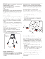
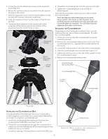
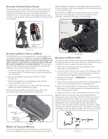
imbalance is very slight. When taking astrophotographs, this balance process can be done for the specific area at which the telescope is pointing to further optimize tracking accuracy. Balancing the Mount in DEC Although the telescope does not track in declination, the telescope should also be balanced in this axis to prevent any sudden motions when the DEC lock lever is loose. To balance the telescope in DEC: 1. Loosen the R.A. clutch lock lever and rotate the telescope so that it is on one side of the mount (i.e., as described in the previous section on "Balancing the Mount in R.A."). 2. Tighten the R.A. lock lever to hold the telescope in place. 3. Loosen the DEC clutch lock lever and rotate the telescope until the tube is parallel to the ground. 4. Release the tube - GRADUALLY - to see which way it rotates around the declination axis. DO NOT LET GO OF THE TELESCOPE TUBE COMPLETELY! 5. Slightly loosen the knobs that holds the telescope to the mounting platform and slide the telescope either forward or backward until it remains stationary when the DEC clutch is loose. Do NOT let go of the telescope tube while the knob on the mounting platform is loose. It may be necessary to rotate the telescope so that the counterweight bar is pointing down before loosening the mounting platform screw. 6. Tighten the knobs on the telescope mounting platform to hold the telescope in place. Like R.A. balance, these are general balance instructions and will reduce undue stress on the mount. When taking astrophotographs, this balance process should be done for the specific area at which the telescope is pointing. Adjusting the Mount In order for a motor drive to track accurately, the telescope's axis of rotation must be parallel to the Earth's axis of rotation, a process known as polar alignment. Polar alignment is achieved NOT by moving the telescope in R.A. or DEC, but by adjusting the mount vertically, which is called altitude, and horizontally, which is called azimuth. This section simply covers the correct movement of the telescope during the polar alignment process. The actual process of polar alignment, that is making the telescope's axis of rotation parallel to the Earth's, is described later in this manual in the section on "Polar Alignment." Adjusting the Mount in Altitude • To increase (raise) the latitude of the polar axis, turn the rear latitude adjustment knob and loosen the front screw (if necessary). • To decrease (lower) the latitude of the polar axis, turn the rear latitude adjustment knob and tighten the front screw (if necessary). The latitude adjustment on the mount has a range from approximately 15° to 70°. It is best to always make final adjustments in latitude by moving the mount against gravity (i.e. using the rear latitude adjustment screw to raise the mount). Adjusting the Mount in Azimuth For rough adjustments in azimuth, simply pick up the telescope and tripod and move it side to side until it is roughly pointing towards north. For fine adjustments in azimuth: 1. Turn the azimuth adjustment knobs located on either side of the azimuth housing (see Fig 2-10). While standing behind the telescope, the knobs are on the front of the mount. • Turning the right adjustment knob clockwise moves the mount toward the right. • Turning the left adjustment knob clockwise moves the mount to the left. Rear Latitude Adjustment Knob Front Latitude Adjustment Screw Azimuth Adjustment Knob Figure 2-10 Both screws push off of the peg on the tripod head, which means you may have to loosen one screw while tightening the other. The screw that holds the equatorial mount to the tripod may have to be loosened slightly. Keep in mind that adjusting the mount is done during the polar alignment process only. Once polar aligned, the mount must NOT be moved. Pointing the telescope is done by moving the mount in right ascension and declination, as described earlier in this manual. Powering the Mount The telescope mount can be powered by the supplied car battery adapter or optional 12v AC adapter. Use only adapters supplied by Celestron. Using any other adapter may damage the electronics or cause the telescope not to operate properly, and will void your manufacturer's warranty. 1. To power the telescope with the car battery adapter (or 12v AC adapter), simply plug the round post into the 12v outlet on the electronic panel and plug the other end into your cars cigarette lighter outlet or portable power supply (see Optional Accessories). 2. Turn on the power to the telescope by flipping the switch, located on the electronics panel, to the "On" position. Hand Control All Celestron computerized telescope come with a hand control designed to give you instant access to all the functions that your telescope has to offer. With automatic slewing to over 40,000 objects, and common sense menu descriptions, even a beginner can master its variety of features in just a few observing sessions. Below is a brief description of the individual components of the computerized hand controller: 1. Liquid Crystal Display (LCD) Window: Has a dual-line, 16 character display screen that is backlit for comfortable viewing of telescope information and scrolling text. 6
-
 1
1 -
2
-
 3
3 -
 4
4 -
 5
5 -
 6
6 -
 7
7 -
 8
8 -
 9
9 -
 10
10 -
 11
11 -
 12
12 -
 13
13 -
14
-
15
-
16
-
17
-
18
-
19
-
20
-
21
-
22
-
23
-
24
-
25
-
26
-
27
-
28
-
29
-
30
-
31
-
32
-
33
-
34
-
35
-
36
-
37
-
38
 |
 |
