Cisco 2620 User Guide - Page 5
Cisco 2621XM and Cisco 2651XM Rear Panel LEDs, Front Panel LEDs, Table 1, Indication - ethernet wic
 |
UPC - 746320181783
View all Cisco 2620 manuals
Add to My Manuals
Save this manual to your list of manuals |
Page 5 highlights
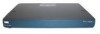
The 2621XM/2651XM Router Figure 3 Cisco 2621XM and Cisco 2651XM Rear Panel LEDs 100 Mbps LED Link LED 100 Mbps LED FDX Link FDX LED LED LED SERIAL 1 CONN SERIAL 0 SEE MANUAL BEFORE INSTALLATION WIC CONN 2A/S 100 Mbps Link W1 FDX 100 Mbps Link SERIAL 1 CONN SERIAL 0 SEE MANUAL BEFORE INSTALLATION WIC CONN 2A/S FDX W0 Cisco 2621 10/100 ETHERNET 0/1 10/100 ETHERNET 0/0 CONSOLE AUX 10/100BASE-T Ethernet 0/1 (RJ-45) 10/100BASE-T Ethernet 0/0 (RJ-45) Auxiliary port (RJ-45) Console port (RJ-45) 99495 Table 1 Cisco 2621XM and Cisco 2651XM Rear Panel LEDs and Descriptions LED LINK FDX 100 Mbps Indication Green Off Green Off Green Off Description An Ethernet link has been established No Ethernet link established The interface is transmitting data in full-duplex mode When off, the interface is transmitting data in half-duplex mode The speed of the interface is 100 Mbps The speed of the interface is 10 Mbps or no link is established Figure 4 shows the front panel LEDs, which provide overall status of the router's operation. The front panel displays whether or not the router is booted, if the redundant power is (successfully) attached and operational, and overall activity/link status. Figure 4 Front Panel LEDs 99496 POWER RPS ACTIVITY Table 2 provides more detailed information conveyed by the LEDs on the front panel of the router: Cisco 2621XM and Cisco 2651XM Modular Access Routers with AIM-VPN/EP FIPS 140-2 Non-Proprietary Security Policy OL-6262-01 5
-
 1
1 -
 2
2 -
 3
3 -
 4
4 -
 5
5 -
 6
6 -
 7
7 -
 8
8 -
 9
9 -
 10
10 -
 11
11 -
12
-
13
-
14
-
15
-
16
-
17
-
18
-
19
-
20
-
21
-
22
-
23
-
24
 |
 |
