Cisco 2620 User Guide - Page 9
Cisco 2621XM and Cisco 2651XM Chassis Removal, Step 1
 |
UPC - 746320181783
View all Cisco 2620 manuals
Add to My Manuals
Save this manual to your list of manuals |
Page 9 highlights
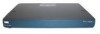
Figure 5 Cisco 2621XM and Cisco 2651XM Chassis Removal The 2621XM/2651XM Router POWER RPS ACTIVITY Cisco 2600 SERIES 99497 Any NM or WIC slot, which is not populated with a NM or WIC, must be populated with an appropriate slot cover in order to operate in a FIPS compliant mode. The slot covers are included with each router, and additional covers may be ordered from Cisco. The same procedure mentioned below to apply tamper evidence labels for NMs and WICs must also be followed to apply tamper evidence labels for the slot covers. Once the router has been configured in to meet FIPS 140-2 Level 2 requirements, the router cannot be accessed without signs of tampering. To seal the system, apply serialized tamper-evidence labels as follows: Step 1 Step 2 Step 3 Step 4 Step 5 Step 6 Step 7 Clean the cover of any grease, dirt, or oil before applying the tamper evidence labels. Alcohol-based cleaning pads are recommended for this purpose. The temperature of the router should be above 10 C. Place the first label on the router as shown in Figure 6. The tamper evidence label should be placed so that the one half of the tamper evidence label covers the enclosure and the other half covers the side of the router. Any attempt to remove the enclosure will leave tamper evidence. Place the second label on the router as shown in Figure 6. The tamper evidence label should be placed so that the one half of the tamper evidence label covers the enclosure and the other half covers the side of the router. Any attempt to remove the enclosure will leave tamper evidence. Place the third label on the router as shown in Figure 6. The tamper evidence label should be placed so that the one half of the label covers the enclosure and the other half covers the Network Module slot. Any attempt to remove a Network Module will leave tamper evidence. Place the fourth label on the router as shown in Figure 6. The tamper evidence label should be placed so that the half of the label covers the enclosure and the other half covers the WAN interface card slot. Any attempt to remove a WAN interface card will leave tamper evidence. Place the fifth label on the router as shown in Figure 6. The tamper evidence label should be placed so that one half of the label covers the enclosure and the other half covers the WAN interface card slot. Any attempt to remove a WAN interface card will leave tamper evidence. The labels completely cure within five minutes. Cisco 2621XM and Cisco 2651XM Modular Access Routers with AIM-VPN/EP FIPS 140-2 Non-Proprietary Security Policy OL-6262-01 9
-
 1
1 -
2
-
3
-
 4
4 -
 5
5 -
 6
6 -
 7
7 -
 8
8 -
 9
9 -
 10
10 -
 11
11 -
 12
12 -
 13
13 -
 14
14 -
15
-
16
-
17
-
18
-
19
-
20
-
21
-
22
-
23
-
24
 |
 |
