Cisco 3845 Hardware Guide - Page 87
Inserting Slot Divider into Network Module Slot Generic Router, Step 2
 |
UPC - 746320981420
View all Cisco 3845 manuals
Add to My Manuals
Save this manual to your list of manuals |
Page 87 highlights
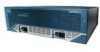
Installing and Removing Slot Dividers Figure 34 Inserting Slot Divider into Network Module Slot (Generic Router) 1 121385 2 1 Insert slot divider 2 Tighten screw so front surface is flush with router rear panel Step 2 Step 3 Push the slot divider into the slot. The slot divider's screw tip and guide pin fit into holes at the back of the slot. Use the number 1 Phillips screwdriver to tighten the attachment screw. When it is fully seated, the slot divider's front surface is flush with the router's rear panel. See Figure 34. Pull gently on the slot divider to check that it is seated securely. OL-5973-01 Installing Network Modules in Cisco 3800 Series Routers 57
-
 1
1 -
2
-
3
-
4
-
5
-
6
-
7
-
8
-
9
-
10
-
11
-
12
-
13
-
14
-
15
-
16
-
17
-
18
-
19
-
20
-
21
-
22
-
23
-
24
-
25
-
26
-
27
-
28
-
29
-
30
-
31
-
32
-
33
-
34
-
35
-
36
-
37
-
38
-
39
-
40
-
41
-
42
-
43
-
44
-
45
-
46
-
47
-
48
-
49
-
50
-
51
-
52
-
53
-
54
-
55
-
56
-
57
-
58
-
59
-
60
-
61
-
62
-
63
-
64
-
65
-
66
-
67
-
68
-
69
-
70
-
71
-
72
-
73
-
74
-
75
-
76
-
77
-
78
-
79
-
80
-
81
-
 82
82 -
 83
83 -
 84
84 -
 85
85 -
 86
86 -
 87
87 -
 88
88 -
 89
89 -
 90
90 -
 91
91 -
 92
92 -
93
-
94
-
95
-
96
-
97
-
98
-
99
-
100
-
101
-
102
-
103
-
104
-
105
-
106
-
107
-
108
-
109
-
110
-
111
-
112
-
113
-
114
-
115
-
116
-
117
-
118
-
119
-
120
-
121
-
122
-
123
-
124
-
125
-
126
-
127
-
128
-
129
-
130
-
131
-
132
-
133
-
134
-
135
-
136
-
137
-
138
 |
 |

Installing and Removing Slot Dividers
57
Installing Network Modules in Cisco 3800 Series Routers
OL-5973-01
Figure 34
Inserting Slot Divider into Network Module Slot (Generic Router)
Step 2
Push the slot divider into the slot. The slot divider’s screw tip and guide pin fit into holes at the back of
the slot. Use the number 1 Phillips screwdriver to tighten the attachment screw. When it is fully seated,
the slot divider’s front surface is flush with the router’s rear panel. See
Figure 34
.
Step 3
Pull gently on the slot divider to check that it is seated securely.
1
Insert slot divider
2
Tighten screw so front surface is flush with
router rear panel
121385
1
2