Cisco 4908G-L3 Installation Guide - Page 81
Starting the Terminal-Emulation Software, Connecting to a Power Source
 |
UPC - 746320303703
View all Cisco 4908G-L3 manuals
Add to My Manuals
Save this manual to your list of manuals |
Page 81 highlights
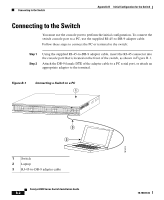
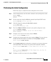
Appendix B Initial Configuration for the Switch Starting the Terminal-Emulation Software Starting the Terminal-Emulation Software Before you power on the switch, start the terminal-emulation session so that you can see the output display from the power-on self-test (POST). The terminal-emulation software-frequently a PC application such as Hyperterminal or ProcommPlus-makes communication between the switch and your PC or terminal possible. Step 1 Step 2 Step 3 Start the terminal-emulation program if you are using a PC or terminal. Start a terminal-emulation session. Configure the baud rate and character format of the PC or terminal to match these console port default characteristics: • 9600 baud • 8 data bits • 1 stop bit • No parity • None (flow control) Connecting to a Power Source Follow these steps to connect to a power source: Step 1 Step 2 If you are using an AC power supply, connect one end of the supplied AC power cord to the power connector on the switch rear panel, and then connect the other end of the power cable to a grounded AC outlet. (See Figure B-1.) If you are using a DC power supply, see the "Connecting DC Power to the Switch" section on page 3-11 for instructions on how to install the DC power supply. 78-18039-02 As the switch powers on, it begins the POST, a series of tests that runs automatically to ensure that the switch functions properly. Catalyst 4900 Series Switch Installation Guide B-3
-
 1
1 -
2
-
3
-
4
-
5
-
6
-
7
-
8
-
9
-
10
-
11
-
12
-
13
-
14
-
15
-
16
-
17
-
18
-
19
-
20
-
21
-
22
-
23
-
24
-
25
-
26
-
27
-
28
-
29
-
30
-
31
-
32
-
33
-
34
-
35
-
36
-
37
-
38
-
39
-
40
-
41
-
42
-
43
-
44
-
45
-
46
-
47
-
48
-
49
-
50
-
51
-
52
-
53
-
54
-
55
-
56
-
57
-
58
-
59
-
60
-
61
-
62
-
63
-
64
-
65
-
66
-
67
-
68
-
69
-
70
-
71
-
72
-
73
-
74
-
75
-
 76
76 -
 77
77 -
 78
78 -
 79
79 -
 80
80 -
 81
81 -
 82
82 -
 83
83 -
 84
84 -
 85
85 -
 86
86 -
87
-
88
-
89
-
90
-
91
-
92
-
93
-
94
-
95
-
96
-
97
-
98
-
99
-
100
-
101
-
102
-
103
-
104
-
105
-
106
-
107
-
108
-
109
-
110
-
111
-
112
-
113
-
114
-
115
-
116
-
117
-
118
-
119
-
120
-
121
-
122
-
123
-
124
-
125
-
126
-
127
-
128
-
129
-
130
-
131
-
132
-
133
-
134
-
135
-
136
-
137
-
138
-
139
-
140
-
141
-
142
 |
 |
