Cisco 7604 Installation Guide - Page 121
Identifying a Rollover Cable, Console Port Mode 1 Signaling and Pinouts
 |
View all Cisco 7604 manuals
Add to My Manuals
Save this manual to your list of manuals |
Page 121 highlights
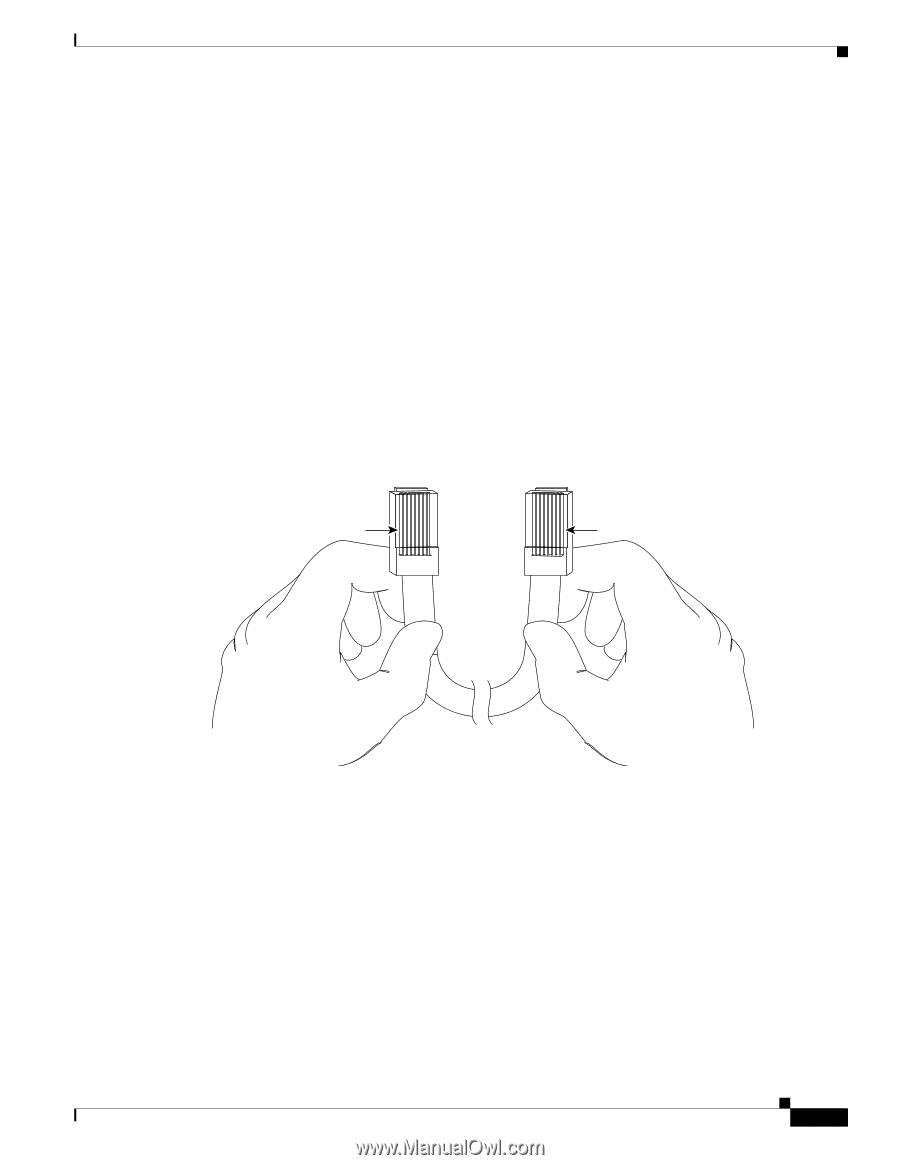
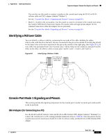
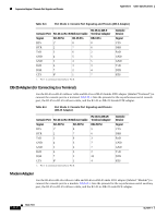
Appendix B Cable Specifications Supervisor Engine 2 Console Port Signals and Pinouts You can also use this mode to connect a modem to the console port using the RJ-45-to-RJ-45 rollover cable and DCE adapter (labeled "Modem"). See the "Console Port Mode 1 Signaling and Pinouts" section on page B-3. • Mode 2-Switch in the out position. Use this mode to connect a terminal to the console port using the Catalyst 5000 family Supervisor Engine III console cable and appropriate adapter for the terminal connection (cable and adapter are not provided). See the "Console Port Mode 2 Signaling and Pinouts" section on page B-5. Identifying a Rollover Cable You can identify a rollover cable by comparing the two ends of the cable. Holding the cables side-by-side, with the tab at the back, the wire connected to the pin on the outside of the left plug should be the same color as the wire connected to the pin on the outside of the right plug. (See Figure B-1.) If your cable was purchased from Cisco Systems, pin 1 will be white on one connector, and pin 8 will be white on the other. (A rollover cable reverses pins 1 and 8, 2 and 7, 3 and 6, and 4 and 5.) Figure B-1 Identifying a Rollover Cable Pin 1 Pin 1 and pin 8 should be the same color Pin 8 H3824 Console Port Mode 1 Signaling and Pinouts This section provides the signaling and pinouts for the console port in mode 1 (console port mode switch in the in position). DB-9 Adapter (for Connecting to a PC) Use the RJ-45-to-RJ-45 rollover cable and RJ-45-to-DB-9 female DTE adapter (labeled "Terminal") to connect the console port to a PC running terminal emulation software. Table B-3 lists the pinouts for the asynchronous serial console port, the RJ-45-to-RJ-45 rollover cable, and the RJ-45-to-DB-9 female DTE adapter. OL-5077-7 Book Title B-3
-
 1
1 -
2
-
3
-
4
-
5
-
6
-
7
-
8
-
9
-
10
-
11
-
12
-
13
-
14
-
15
-
16
-
17
-
18
-
19
-
20
-
21
-
22
-
23
-
24
-
25
-
26
-
27
-
28
-
29
-
30
-
31
-
32
-
33
-
34
-
35
-
36
-
37
-
38
-
39
-
40
-
41
-
42
-
43
-
44
-
45
-
46
-
47
-
48
-
49
-
50
-
51
-
52
-
53
-
54
-
55
-
56
-
57
-
58
-
59
-
60
-
61
-
62
-
63
-
64
-
65
-
66
-
67
-
68
-
69
-
70
-
71
-
72
-
73
-
74
-
75
-
76
-
77
-
78
-
79
-
80
-
81
-
82
-
83
-
84
-
85
-
86
-
87
-
88
-
89
-
90
-
91
-
92
-
93
-
94
-
95
-
96
-
97
-
98
-
99
-
100
-
101
-
102
-
103
-
104
-
105
-
106
-
107
-
108
-
109
-
110
-
111
-
112
-
113
-
114
-
115
-
 116
116 -
 117
117 -
 118
118 -
 119
119 -
 120
120 -
 121
121 -
 122
122 -
 123
123 -
 124
124 -
 125
125 -
 126
126 -
127
-
128
-
129
-
130
-
131
-
132
-
133
-
134
-
135
-
136
-
137
-
138
 |
 |