Cisco 7604 Installation Guide - Page 85
when servicing.
 |
View all Cisco 7604 manuals
Add to My Manuals
Save this manual to your list of manuals |
Page 85 highlights
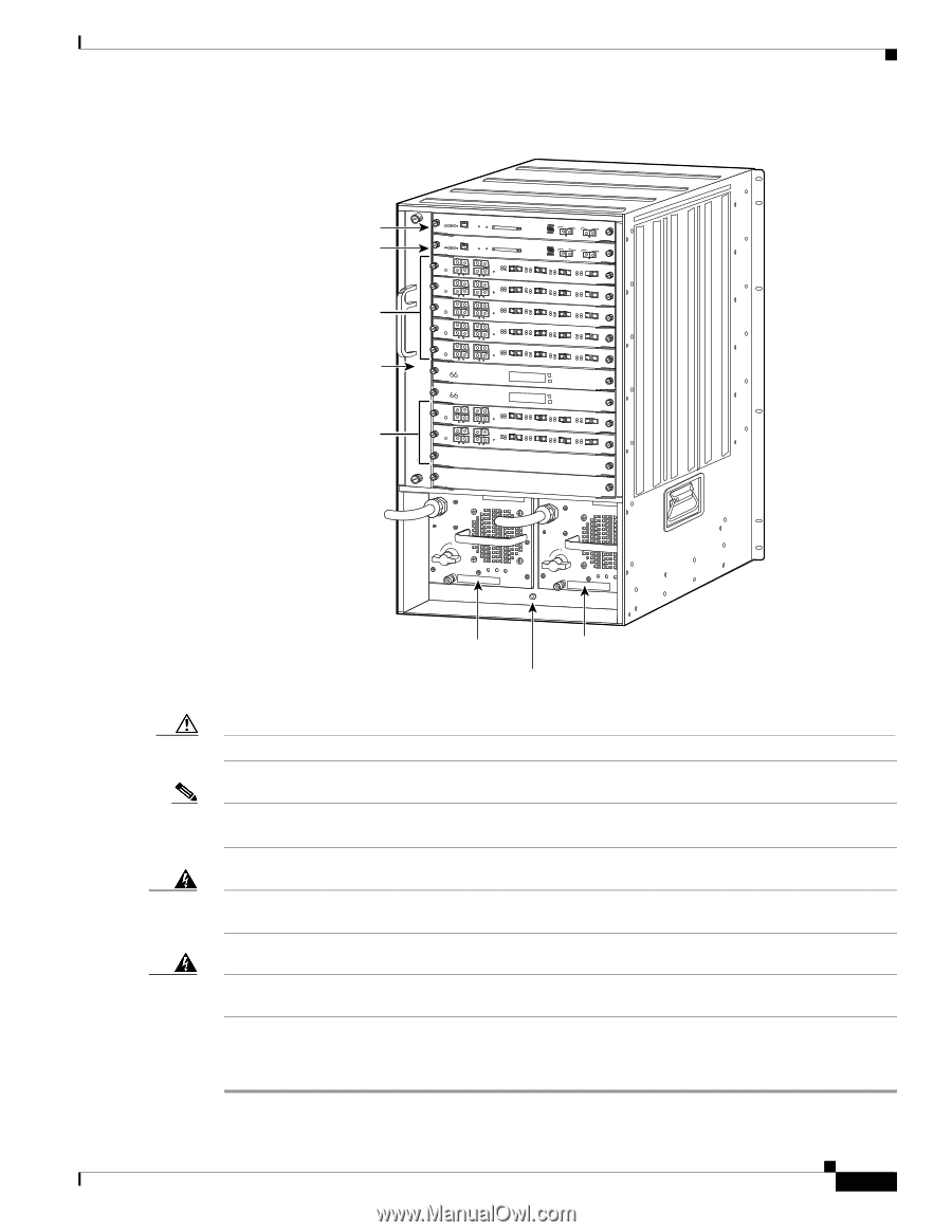
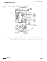
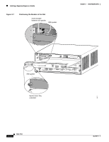
Chapter 3 Installing Modules Figure 3-5 Slot Numbers on Cisco 7613 Router Installing a Supervisor Engine or a Module Supervisor engine Redundant supervisor engine OSMs Fan assembly OSMs 1 2 3 4 5 6 7 8 9 10 11 FAN STATUS 12 WS-X6K-SUP2-2GE STATUS SYSTEMCONSOLPEWR MGRMETSET SUPERVISOR2 CONSOLE CONSOLE PORT MODE WS-X6K-SUP2-2GE STATUS SYSTEMCONSOLPEWR MGRMETSET SUPERVISOR2 CONSOLE CONSOLE PORT MODE OSM-40C12-POS-MM 1 STATUS 2 OC12 POS MM OSM-40C12-POS-MM LINK 1 1 STATUS 2 OC12 POS MM OSM-40C12-POS-MM LINK 1 1 STATUS 2 OC12 POS MM OSM-40C12-POS-MM LINK 1 1 STATUS 2 OC12 POS MM OSM-40C12-POS-MM LINK 1 1 STATUS OC12 POS MM 2 LINK 1 WS-C6500-SFM 3 LINK 2 4 LINK 3 3 LINK 2 4 LINK 3 3 LINK 2 4 LINK 3 3 LINK 2 4 LINK 3 3 LINK 2 4 LINK 3 PCMCIA EJECT Switch 100% Load 1% PORT 1 LINK PORT 2 LINK PCMCIA LINK 4 RESET ACTIVE TX CAARLRAIERRM RX EJECT RX TX ACTIVE TX PORT 1 CAARLRAIERRM RX Switch 100% Load 1% RX TX ACTIVE TX PORT 2 CAARLRAIERRM RX PORT 1 LINK RX TX PORT 3 ACTIVE TX CAARLRAIERRM RX PORT 2 LINK RX TX LINK 4 RESET ACTIVE TX CAARLRAIERRM RX RX TX ACTIVE TX PORT 1 CAARLRAIERRM RX RX TX ACTIVE TX PORT 2 CAARLRAIERRM RX RX TX PORT 3 ACTIVE TX CAARLRAIERRM RX RX TX LINK 4 RESET ACTIVE TX CAARLRAIERRM RX RX TX ACTIVE TX PORT 1 CAARLRAIERRM RX RX TX ACTIVE TX PORT 2 CAARLRAIERRM RX RX TX PORT 3 ACTIVE TX CAARLRAIERRM RX RX TX LINK 4 RESET ACTIVE TX CAARLRAIERRM RX RX TX ACTIVE TX PORT 1 CAARLRAIERRM RX RX TX ACTIVE TX PORT 2 CAARLRAIERRM RX RX TX PORT 3 ACTIVE TX CAARLRAIERRM RX RX TX LINK 4 RESET ACTIVE TX CAARLRAIERRM RX RX TX ACTIVE TX PORT 1 CAARLRAIERRM RX RX TX ACTIVE TX PORT 2 CAARLRAIERRM RX RX TX PORT 3 ACTIVE TX CAARLRAIERRM RX RX TX STATUS ACTIVE SELECT NEXT SWITCH FABRIC MDL WS-C6500-SFM STATUS ACTIVE SELECT SWITCH FABRIC MDL OSM-40C12-POS-MM 1 STATUS 2 OC12 POS MM OSM-40C12-POS-MM LINK 1 STATUS OC12 POS MM 1 2 LINK 1 3 LINK 2 4 LINK 3 3 LINK 2 4 LINK 3 LINK 4 RESET ACTIVE TX CAARLRAIERRM RX RX TX ACTIVE TX PORT 1 CAARLRAIERRM RX RX TX ACTIVE TX PORT 2 CAARLRAIERRM RX RX TX PORT 3 ACTIVE TX CAARLRAIERRM RX RX TX LINK 4 RESET ACTIVE TX CAARLRAIERRM RX RX TX ACTIVE TX PORT 1 CAARLRAIERRM RX RX TX ACTIVE TX PORT 2 CAARLRAIERRM RX RX TX PORT 3 ACTIVE TX CAARLRAIERRM RX RX TX NEXT 13 91093 o o INPUT OK FAN OUTPUT OK FAIL INPUT OK FAN OUTPUT OK FAIL Power supply 1 Power supply 2 (redundant) ESD ground strap connection Caution To prevent ESD damage, handle modules by the carrier edges only. Note Supervisor Engine 2 is installed in slot 1 and slot 2. Supervisor Engine 720s and Route Switch Processor 720s are installed in slot 7 and slot 8. Warning Hazardous voltage or energy is present on the backplane when the system is operating. Use caution when servicing. Warning Invisible laser radiation may be emitted from disconnected fibers or connectors. Do not stare into beams or view directly with optical instruments. To install a supervisor engine, OSM, Catalyst 6000 family module, or SIP in the Cisco 7600 series router, perform these steps: Step 1 Choose a slot for the supervisor engine or module. OL-5077-7 Book Title 3-7
-
 1
1 -
2
-
3
-
4
-
5
-
6
-
7
-
8
-
9
-
10
-
11
-
12
-
13
-
14
-
15
-
16
-
17
-
18
-
19
-
20
-
21
-
22
-
23
-
24
-
25
-
26
-
27
-
28
-
29
-
30
-
31
-
32
-
33
-
34
-
35
-
36
-
37
-
38
-
39
-
40
-
41
-
42
-
43
-
44
-
45
-
46
-
47
-
48
-
49
-
50
-
51
-
52
-
53
-
54
-
55
-
56
-
57
-
58
-
59
-
60
-
61
-
62
-
63
-
64
-
65
-
66
-
67
-
68
-
69
-
70
-
71
-
72
-
73
-
74
-
75
-
76
-
77
-
78
-
79
-
 80
80 -
 81
81 -
 82
82 -
 83
83 -
 84
84 -
 85
85 -
 86
86 -
 87
87 -
 88
88 -
 89
89 -
 90
90 -
91
-
92
-
93
-
94
-
95
-
96
-
97
-
98
-
99
-
100
-
101
-
102
-
103
-
104
-
105
-
106
-
107
-
108
-
109
-
110
-
111
-
112
-
113
-
114
-
115
-
116
-
117
-
118
-
119
-
120
-
121
-
122
-
123
-
124
-
125
-
126
-
127
-
128
-
129
-
130
-
131
-
132
-
133
-
134
-
135
-
136
-
137
-
138
 |
 |