Cisco AIR-BR350-A-K9 Hardware Installation Guide - Page 15
Indicator Lights - aironet 350 wireless bridge
 |
UPC - 746320634890
View all Cisco AIR-BR350-A-K9 manuals
Add to My Manuals
Save this manual to your list of manuals |
Page 15 highlights
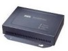
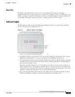
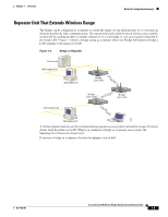
Chapter 1 Overview Key Features Serial Port The bridge's serial port provides console access to its management system. Use a nine-pin, straight-through, male-to-female serial cable to connect your computer's COM 1 or COM 2 port to the bridge's serial port. Assign the following port settings to a terminal emulator to open the management system pages: 9600 baud, 8 data bits, No parity, 1 stop bit, and Xon/Xoff flow control. Indicator Lights The three indicator lights on top of the bridge report Ethernet activity, association status, and radio activity. The indicators are labeled in Figure 1-1. Figure 1-1 Indicator Lights on the Bridge CISCO AIRONET 350 SERIES WIRELESS BRIDGE ETHERNET ACTIVITY ASSOCIATION STATUS RADIO ACTIVITY Ethernet Status Radio 48767 • The Ethernet indicator signals traffic on the wired LAN, or Ethernet infrastructure. This indicator blinks green when a packet is received or transmitted over the Ethernet infrastructure. • The status indicator signals operational status. Blinking green indicates that the bridge is operating normally but is not associated with any wireless devices. Steady green indicates that the bridge is associated with a wireless client. For repeater bridges, blinking 1/2 on, 1/2 off indicates the repeater is not associated with the root bridge; blinking 7/8 on, 1/8 off indicates that the repeater is associated with the root bridge but no client devices are associated with the repeater; steady green indicates that the repeater is associated with the root bridge and client devices are associated with the repeater. • The radio indicator blinks green to indicate radio traffic activity. The light is normally off, but it blinks green whenever a packet is received or transmitted over the bridge's radio. OL-1412-01 Cisco Aironet 350 Series Bridge Hardware Installation Guide 1-3
-
 1
1 -
2
-
3
-
4
-
5
-
6
-
7
-
8
-
9
-
 10
10 -
 11
11 -
 12
12 -
 13
13 -
 14
14 -
 15
15 -
 16
16 -
 17
17 -
 18
18 -
 19
19 -
 20
20 -
21
-
22
-
23
-
24
-
25
-
26
-
27
-
28
-
29
-
30
-
31
-
32
-
33
-
34
-
35
-
36
-
37
-
38
-
39
-
40
-
41
-
42
-
43
-
44
-
45
-
46
-
47
-
48
-
49
-
50
-
51
-
52
-
53
-
54
-
55
-
56
-
57
-
58
-
59
-
60
-
61
-
62
-
63
-
64
-
65
-
66
-
67
-
68
-
69
-
70
-
71
-
72
-
73
-
74
-
75
-
76
 |
 |
