Cisco AIR-BR350-A-K9 Hardware Installation Guide - Page 19
Bridge Specifications - aironet air
 |
UPC - 746320634890
View all Cisco AIR-BR350-A-K9 manuals
Add to My Manuals
Save this manual to your list of manuals |
Page 19 highlights
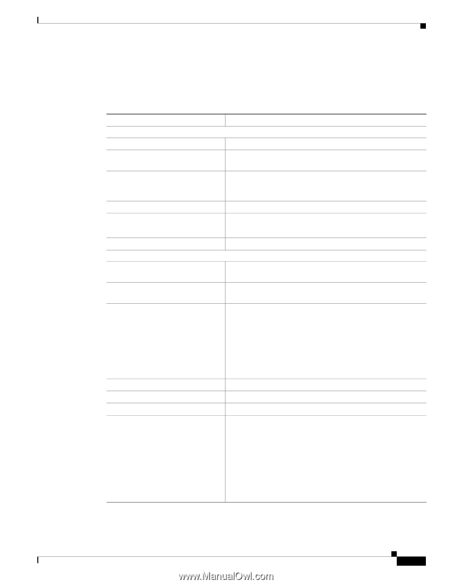
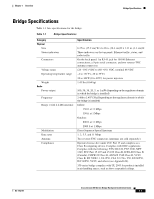
Chapter 1 Overview Bridge Specifications Bridge Specifications Table 1-1 lists specifications for the bridge. Table 1-1 Bridge Specifications Category Physical Size Status indicators Connectors Voltage range Operating temperature range Weight Radio Power output Frequency Range ( with 2.2 dBi antenna) Modulation Data rates Antenna Compliance Specification 6.25 in. (15.9 cm) W x 6.42 in. (16.3 cm) D x 1.31 in. (3.3 cm) H Three indicators on the top panel: Ethernet traffic, status, and radio traffic On the back panel: An RJ-45 jack for 10/100 Ethernet connections; a 9-pin serial connector; and two reverse-TNC antenna connectors (24 -10%) VDC to (60 -0%) VDC, nominal 48 VDC -4 to 131oF (-20 to 55oC) 32 to 104oF (0 to 40oC) for power injectors 1.43 lbs (0.64 kg) 100, 50, 30, 20, 5, or 1 mW (depending on the regulatory domain in which the bridge is installed) 2.400 to 2.497 GHz (Depending on the regulatory domain in which the bridge is installed) Indoor: 150 ft at 11 Mbps 350 ft at 1 Mbps Outdoor: 800 ft at 11 Mbps 2000 ft at 1 Mbps Direct Sequence Spread Spectrum 1, 2, 5.5, and 11 Mbps Two reverse-TNC connectors (antennas are sold separately). Operates license-free under FCC Part 15 and complies as a Class B computing device. Complies with DOC regulations. Complies with the following: ETS 300.328, FTZ 2100, MPT 1349, FCC Part 15.107 and 15.109 Class B, ICES-003 Class B (Canada), CISPR 22 Class B, AS/NZS 3548 Class B, VCCI Class B, EN 50082-1, UL1950, CSA 22.2 No. 950, EN 60950, IEC 60950, VCCI, and others (see Appendix B). 350 series bridge complies with UL 2043 for products installed in air handling spaces, such as above suspended ceilings. OL-1412-01 Cisco Aironet 350 Series Bridge Hardware Installation Guide 1-7
-
 1
1 -
2
-
3
-
4
-
5
-
6
-
7
-
8
-
9
-
10
-
11
-
12
-
13
-
 14
14 -
 15
15 -
 16
16 -
 17
17 -
 18
18 -
 19
19 -
 20
20 -
 21
21 -
 22
22 -
 23
23 -
 24
24 -
25
-
26
-
27
-
28
-
29
-
30
-
31
-
32
-
33
-
34
-
35
-
36
-
37
-
38
-
39
-
40
-
41
-
42
-
43
-
44
-
45
-
46
-
47
-
48
-
49
-
50
-
51
-
52
-
53
-
54
-
55
-
56
-
57
-
58
-
59
-
60
-
61
-
62
-
63
-
64
-
65
-
66
-
67
-
68
-
69
-
70
-
71
-
72
-
73
-
74
-
75
-
76
 |
 |