Cisco AIR-BR350-A-K9 Hardware Installation Guide - Page 16
Network Configuration Examples
 |
UPC - 746320634890
View all Cisco AIR-BR350-A-K9 manuals
Add to My Manuals
Save this manual to your list of manuals |
Page 16 highlights
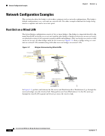
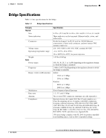
Network Configuration Examples Chapter 1 Overview Network Configuration Examples This section describes the bridge's role in three common wireless network configurations. The bridge's default configuration is as a root unit on a wired LAN. The other examples illustrate the bridge being used as a repeater unit and as an access point. Root Unit on a Wired LAN The typical bridge configuration consists of two or more bridges. One bridge is connected directly to the main wired LAN (referred to as a root unit) and the other bridge or bridges (referred to as non-root units) are attached to remote LAN segments (usually in different buildings). Only one bridge in a wireless LAN can be set to root, all other bridges must be set to non-root. Figure 1-2 shows a bridge acting as a root unit on a wired LAN communicating with other non-root bridges on remote LANs. Figure 1-2 Bridges Interconnecting Wired LANs File server LAN segment A Workstation A W I RCEILSECSOS AAICRCOE SN SETP 3O I50N STERIES RADIOAASCSTIOVCIEITTAYTHIEORNNSETTATAUCSTIVITY LEFT SERIAL PORT ONLINE POWER ETHERNET RIGHT/PRIMARY Bridge (root unit) W I RCEILSECSOS AAICRCOE SN SETP 3O I50N STERIES RADIOAASCSTIOVCIEITTAYTHIEORNNSETTATAUCSTIVITY LAN segment B LEFT SERIAL PORT ONLINE POWER ETHERNET RIGHT/PRIMARY Bridge (non-root) W I RCEILSECSOS AAICRCOE SN SETP 3O I50N STERIES RADIOAASCSTIOVCIEITTAYTHIEORNNSETTATAUCSTIVITY Workstation B LAN segment C LEFT SERIAL PORT ONLINE POWER ETHERNET RIGHT/PRIMARY Bridge (non-root) 53089 Workstation C In Figure 1-2, packets sent between the file server and Workstation B or Workstation C go through the non-root bridges over the wireless link. Data packets sent from Workstation A to the file server go through the wired LAN segment and do not go across the wireless link. Cisco Aironet 350 Series Bridge Hardware Installation Guide 1-4 OL-1412-01
-
 1
1 -
2
-
3
-
4
-
5
-
6
-
7
-
8
-
9
-
10
-
 11
11 -
 12
12 -
 13
13 -
 14
14 -
 15
15 -
 16
16 -
 17
17 -
 18
18 -
 19
19 -
 20
20 -
 21
21 -
22
-
23
-
24
-
25
-
26
-
27
-
28
-
29
-
30
-
31
-
32
-
33
-
34
-
35
-
36
-
37
-
38
-
39
-
40
-
41
-
42
-
43
-
44
-
45
-
46
-
47
-
48
-
49
-
50
-
51
-
52
-
53
-
54
-
55
-
56
-
57
-
58
-
59
-
60
-
61
-
62
-
63
-
64
-
65
-
66
-
67
-
68
-
69
-
70
-
71
-
72
-
73
-
74
-
75
-
76
 |
 |
