Cisco ASR1004-10G/K9 Hardware Installation Guide - Page 126
RJ-45 Cable Pinouts, Patch Panel Cabling, 24-Port Channelized T1/E1/J1 CEoP SPA Patch Panel
 |
View all Cisco ASR1004-10G/K9 manuals
Add to My Manuals
Save this manual to your list of manuals |
Page 126 highlights
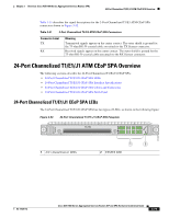
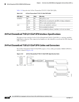
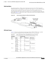
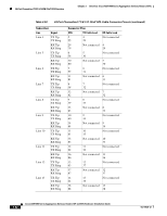
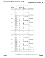
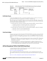
24-Port Channelized T1/E1/J1 ATM CEoP SPA Overview Chapter 3 Overview: Cisco ASR 1000 Series Aggregation Services Routers SPAs Table 3-53 24-Port Channelized T1/E1/J1 CEoP SPA Cable Connector Pinouts (continued) Subscriber Line Signal Line 24 TX Tip TX Ring RX Tip RX Ring Connector Pins SPA TX Cable Lead 25 24 75 49 49 Not connected 99 RX Cable Lead Not connected 24 49 RJ-45 Cable Pinouts T1 lines from individual subscribers are attached to the RJ-45 connectors on the front of the 24-port patch panel. Each RJ-45 port accommodates an individual T1 subscriber line. Pins 1 and 2 and 4 and 5 of the RJ-45 connectors are used for the 24-port CEoP SPA's Transmit (TX) and Receive (RX) signals. Depending on how the cable is installed between the SPA and its patch panel (rear), the RJ-45 connectors operate as follows: • If the TX cable lead is connected to Transmit on the patch panel and RX is connected to Receive: - The SPA's TX signals are transmitted on RJ-45 pins 1 (ring) and 2 (tip). - The SPA's RX signals are received on RJ-45 pins 4 (ring) and 5 (tip). • If the TX cable lead is connected to Receive on the patch panel and RX is connected to Transmit: - RJ-45 pins 1 and 2 are used for the SPA's RX signal. - RJ-45 pins 4 and 5 are used for the SPA's TX signal. Patch Panel Cabling If you are connecting two 24-Port Channelized T1/E1/J1 CEoP SPAs to each other, you must cable both the SPA's patch panels together using a T1 crossover cable or a T1 straight through cable. The type of cable you use (crossover or straight through) depends on how the CEoP SPAs are cabled to their patch panels: • If both the CEoP SPAs are connected to their patch panels in the same manner (TX to Transmit and RX to Receive, or TX to Receive and RX to Transmit), use a T1 crossover cable to connect the patch panels to each other. • If both the CEoP SPAs are connected to their patch panels in a different configuration (TX to Transmit and RX to Receive on one SPA, and TX to Receive and RX to Transmit on the other SPA), use a T1 straight through cable (standard RJ-45 patch cable) between the patch panels. 24-Port Channelized T1/E1/J1 CEoP SPA Patch Panel A 24-port channelized T1/E1/J1 CEoP SPA patch panel with the DCC2484/25T1-S part number is available from Optical Cable Corporation (OCC) at: http://www.occfiber.com/main/index.php This is a shielded rack mount 24-port patch panel, 2RU, accessory component for the Cisco PID SPA-24CHT1-CE-ATM. You can view the image of patch panel with the DCC2484/25T1-S part number at: http://www.occfiber.com/main/index.php?m=1&p=2&s=Y&l=en&it=54&i=193 3-84 Cisco ASR 1000 Series Aggregation Services Routers SIP and SPA Hardware Installation Guide OL-14126-12
-
 1
1 -
2
-
3
-
4
-
5
-
6
-
7
-
8
-
9
-
10
-
11
-
12
-
13
-
14
-
15
-
16
-
17
-
18
-
19
-
20
-
21
-
22
-
23
-
24
-
25
-
26
-
27
-
28
-
29
-
30
-
31
-
32
-
33
-
34
-
35
-
36
-
37
-
38
-
39
-
40
-
41
-
42
-
43
-
44
-
45
-
46
-
47
-
48
-
49
-
50
-
51
-
52
-
53
-
54
-
55
-
56
-
57
-
58
-
59
-
60
-
61
-
62
-
63
-
64
-
65
-
66
-
67
-
68
-
69
-
70
-
71
-
72
-
73
-
74
-
75
-
76
-
77
-
78
-
79
-
80
-
81
-
82
-
83
-
84
-
85
-
86
-
87
-
88
-
89
-
90
-
91
-
92
-
93
-
94
-
95
-
96
-
97
-
98
-
99
-
100
-
101
-
102
-
103
-
104
-
105
-
106
-
107
-
108
-
109
-
110
-
111
-
112
-
113
-
114
-
115
-
116
-
117
-
118
-
119
-
120
-
 121
121 -
 122
122 -
 123
123 -
 124
124 -
 125
125 -
 126
126 -
 127
127 -
 128
128 -
 129
129 -
 130
130 -
 131
131 -
132
-
133
-
134
-
135
-
136
-
137
-
138
-
139
-
140
-
141
-
142
-
143
-
144
-
145
-
146
-
147
-
148
-
149
-
150
-
151
-
152
-
153
-
154
-
155
-
156
-
157
-
158
-
159
-
160
-
161
-
162
-
163
-
164
-
165
-
166
-
167
-
168
-
169
-
170
-
171
-
172
-
173
-
174
-
175
-
176
-
177
-
178
-
179
-
180
-
181
-
182
-
183
-
184
-
185
-
186
-
187
-
188
 |
 |
