Cisco PAP2T User Guide - Page 4
List of s - setup
 |
View all Cisco PAP2T manuals
Add to My Manuals
Save this manual to your list of manuals |
Page 4 highlights
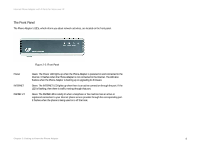
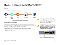
Analog Telephone Adapter with 2 FXS Ports List of Figures Figure 2-1: Back Panel 3 Figure 2-2: Front Panel 4 Figure 3-1: Connection Diagram of a Typical Setup 5 Figure 3-2: Connect the RJ-11 Telephone Cable 5 Figure 3-3: Connect the Ethernet Network Cable 6 Figure 3-4: Connect the Power Adapter 6
-
 1
1 -
 2
2 -
 3
3 -
 4
4 -
 5
5 -
 6
6 -
 7
7 -
 8
8 -
 9
9 -
 10
10 -
11
-
12
-
13
-
14
-
15
-
16
-
17
-
18
-
19
-
20
-
21
-
22
-
23
-
24
-
25
-
26
-
27
-
28
-
29
-
30
-
31
-
32
-
33
-
34
-
35
-
36
 |
 |

Analog Telephone Adapter with 2 FXS Ports
List of Figures
Figure 2-1: Back Panel . . . . . . . . . . . . . . . . . . . . . . . . . . . . . . . . . . . . . . . . . . . . 3
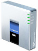
Figure 2-2: Front Panel . . . . . . . . . . . . . . . . . . . . . . . . . . . . . . . . . . . . . . . . . . . . 4
Figure 3-1: Connection Diagram of a Typical Setup . . . . . . . . . . . . . . . . . . . . . . 5
Figure 3-2: Connect the RJ-11 Telephone Cable. . . . . . . . . . . . . . . . . . . . . . . . . 5
Figure 3-3: Connect the Ethernet Network Cable . . . . . . . . . . . . . . . . . . . . . . . . 6
Figure 3-4: Connect the Power Adapter . . . . . . . . . . . . . . . . . . . . . . . . . . . . . . . 6