Cisco SGE2010P Administration Guide - Page 11
CAUTION, corresponding Act/Link LED will light up on the Ethernet switch. If a port has an active - console
 |
UPC - 745883581283
View all Cisco SGE2010P manuals
Add to My Manuals
Save this manual to your list of manuals |
Page 11 highlights
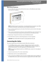
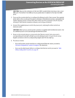
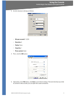
Connecting Devices to the SGE2010/SGE2010P Connecting the Cables CAUTION: Observe the orientation of the mini-GBIC module before inserting it into a miniGBIC port. The bottom mini-GBIC ports are upside down in relation to the top mini-GBIC ports. 5. If you use the console interface to configure the Ethernet switch, then connect the supplied serial cable to the console port (located on the back of the Ethernet switch), and tighten the captive retaining screws. Connect the other end to your PC's serial port. (The PC must be running VT100 terminal emulation software, such as HyperTerminal.) 6. Connect the supplied power cord to the power port, and plug the other end into an electrical outlet. CAUTION: Make sure you use the power cord that is supplied with the Ethernet switch. Use of a different power cord could damage the Ethernet switch. 7. Power on the network devices connected to the Ethernet switch. Each active port's corresponding Act/Link LED will light up on the Ethernet switch. If a port has an active Gigabit connection, then its corresponding Gigabit LED will also light up. 8. Proceed as needed: • If you will use the console interface to configure the Ethernet switch, proceed to "Console Configuration" section on page 33 for directions. • If you use the Web-based Utility to configure the Ethernet switch, proceed to "Web Utility Configuration" section on page 50. SGE2010/SGE2010P Administration Guide 8
-
 1
1 -
2
-
3
-
4
-
5
-
 6
6 -
 7
7 -
 8
8 -
 9
9 -
 10
10 -
 11
11 -
 12
12 -
 13
13 -
 14
14 -
 15
15 -
 16
16 -
17
-
18
-
19
-
20
-
21
-
22
-
23
-
24
-
25
-
26
-
27
-
28
-
29
-
30
-
31
-
32
-
33
-
34
-
35
-
36
-
37
-
38
-
39
-
40
-
41
-
42
-
43
-
44
-
45
-
46
-
47
-
48
-
49
-
50
-
51
-
52
-
53
-
54
-
55
-
56
-
57
-
58
-
59
-
60
-
61
-
62
-
63
-
64
-
65
-
66
 |
 |
