Cisco SGE2010P Administration Guide - Page 6
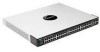
SGE2010/P Back Panel, Feature, Description - 48 port gigabit switch
 |
UPC - 745883581283
View all Cisco SGE2010P manuals
Add to My Manuals
Save this manual to your list of manuals |
Page 6 highlights
Getting to Know the SGE2010/SGE2010P Feature 1-48 miniGBIC1-4 Description The Switch is equipped with 48 auto-sensing, Ethernet (802.3) network ports, which use RJ-45 connectors. The Fast Ethernet ports support network speeds of 10Mbps, 100Mbps, or 1000Mbps. They can operate in half and full-duplex modes. Auto-sensing technology enables each port to automatically detect the speed of the device connected to it, and adjust its speed and duplex accordingly. The switch can deliver a maximum of 15.4W to a PoE port. With regular AC power supply, there is 360W available to all PoE ports, and 280W available with redundant power supply. Ports 45, 46, 47 and 48 are shared with miniGBIC1, miniGBIC2, miniGBIC3, and miniGBIC4, respectively. NOTE: A switch is in stacking mode by default. In stacking mode, ports 24 and 48 are reserved for use as stacking ports. For more information about stacking, refer to the SFE2010/SGE2010 Reference Guide. The switch provides four mini-GBIC ports. The mini-GBIC (gigabit interface converter) port is a connection point for a mini-GBIC expansion module, so the Switch can be uplinked via fiber to another switch. Each mini-GBIC port provides a link to a high-speed network segment or individual workstation at speeds of up to 1000Mbps. Use the Linksys MGBT1, MGBSX1, or MGBLH1 mini-GBIC modules with the switch. The MGBSX1 and the MGBLH1 require fiber cabling with LC connectors, while the MGBT1 requires a Category 5e Ethernet cable with an RJ-45 connector. NOTE: If shared ports are both connected, then the miniGBIC port has priority. SGE2010/P Back Panel Feature Power Console RPS Description The Power port is where you will connect the power cord. The Console port is where you can connect a serial cable to a PC's serial port for configuration using your PC's HyperTerminal program. Refer to Chapter 4: Using the Console Interface for Configuration for more information. Redundant Power Supply (Linksys RPS1000) SGE2010/SGE2010P Administration Guide 3
-
 1
1 -
 2
2 -
 3
3 -
 4
4 -
 5
5 -
 6
6 -
 7
7 -
 8
8 -
 9
9 -
 10
10 -
 11
11 -
 12
12 -
13
-
14
-
15
-
16
-
17
-
18
-
19
-
20
-
21
-
22
-
23
-
24
-
25
-
26
-
27
-
28
-
29
-
30
-
31
-
32
-
33
-
34
-
35
-
36
-
37
-
38
-
39
-
40
-
41
-
42
-
43
-
44
-
45
-
46
-
47
-
48
-
49
-
50
-
51
-
52
-
53
-
54
-
55
-
56
-
57
-
58
-
59
-
60
-
61
-
62
-
63
-
64
-
65
-
66
 |
 |
