Cisco WS-C3560E-48TD-E-RF Installation Guide - Page 71
Mounting the Switch in a Rack, Attaching the Optional Cable Guide
 |
UPC - 882658132629
View all Cisco WS-C3560E-48TD-E-RF manuals
Add to My Manuals
Save this manual to your list of manuals |
Page 71 highlights
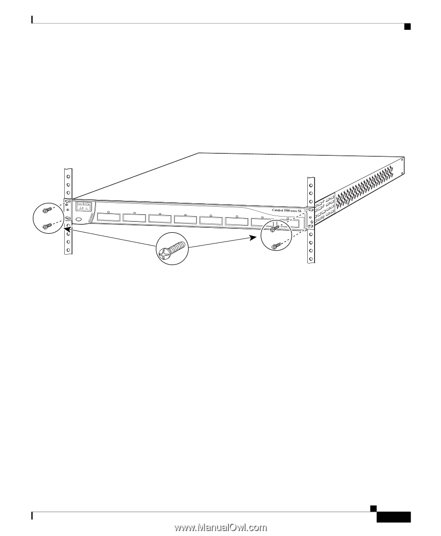
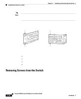
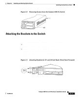
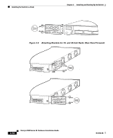
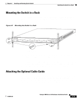
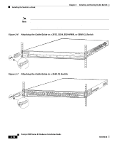
Chapter 2 Installing and Starting Up the Switch Installing the Switch in a Rack Mounting the Switch in a Rack After the brackets are attached to the switch, use the four supplied number-12 Phillips machine screws to securely attach the brackets to the rack, as shown in Figure 2-5. Figure 2-5 Mounting the Switch in a Rack 26233 1 SYSTEM 2 3 RPS 4 5 MODE STATUS 6 7 UTIL 8 DUPLX SPEED Phillips machine screws After the switch is mounted in the rack, attach the power cord to the switch. If you are using the Cisco RPS, see the Cisco RPS documentation for installation instructions. After the power is connected, the System LED turns amber for 2 seconds, and then it flashes green while the switch completes the series of POST tests described in the "Powering On the Switch and Running POST" section on page 2-17. Attaching the Optional Cable Guide We recommend attaching the cable guides to prevent the cables from obscuring the front panel of the switch and the other devices installed in the rack. If the switch is in a 19-inch or 24-inch rack, use the supplied black screw, as shown in Figure 2-6, to attach the cable guide to the left or right bracket. 78-6456-04 Catalyst 3500 Series XL Hardware Installation Guide 2-13
-
 1
1 -
2
-
3
-
4
-
5
-
6
-
7
-
8
-
9
-
10
-
11
-
12
-
13
-
14
-
15
-
16
-
17
-
18
-
19
-
20
-
21
-
22
-
23
-
24
-
25
-
26
-
27
-
28
-
29
-
30
-
31
-
32
-
33
-
34
-
35
-
36
-
37
-
38
-
39
-
40
-
41
-
42
-
43
-
44
-
45
-
46
-
47
-
48
-
49
-
50
-
51
-
52
-
53
-
54
-
55
-
56
-
57
-
58
-
59
-
60
-
61
-
62
-
63
-
64
-
65
-
 66
66 -
 67
67 -
 68
68 -
 69
69 -
 70
70 -
 71
71 -
 72
72 -
 73
73 -
 74
74 -
 75
75 -
 76
76 -
77
-
78
-
79
-
80
-
81
-
82
-
83
-
84
-
85
-
86
-
87
-
88
-
89
-
90
-
91
-
92
-
93
-
94
-
95
-
96
-
97
-
98
-
99
-
100
-
101
-
102
-
103
-
104
-
105
-
106
-
107
-
108
-
109
-
110
-
111
-
112
-
113
-
114
-
115
-
116
-
117
-
118
-
119
-
120
-
121
-
122
-
123
-
124
-
125
-
126
-
127
-
128
-
129
-
130
-
131
-
132
-
133
-
134
-
135
-
136
-
137
-
138
-
139
-
140
-
141
-
142
-
143
-
144
-
145
-
146
-
147
-
148
-
149
-
150
-
151
-
152
-
153
-
154
-
155
-
156
-
157
-
158
-
159
-
160
 |
 |