Cisco WS-X45-SUP6-E Hardware Maintenance Manual - Page 20
Series Specifications, serial, single-mode and multimode Fiber Distributed Data Interface FDDI - memory
 |
UPC - 882658167621
View all Cisco WS-X45-SUP6-E manuals
Add to My Manuals
Save this manual to your list of manuals |
Page 20 highlights
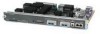
Series Specifications Figure 1-1 shows the front panel of a Cisco 4000 series router. Figure 1-1 Cisco 4000 Series Chassis-Front Panel 1 DATA OK 2 DATA OK 3 DATA OK OK POWER SERIES H3590 Series Specifications Design specifications for the Cisco 4000 series follow: • Modular router platform • Flash memory capability • User-upgradable network processor modules, shared memory, and processor local memory • Hardware thermal alarm to warn of excessively high operating temperature • Rack-mountable in either a standard 19-inch rack or telco rack • Wall, desktop, or desk-side mountable • Support for up to three network processor modules at a time, including Ethernet, Token Ring, serial, single-mode and multimode Fiber Distributed Data Interface (FDDI), ISDN BRI, G.703, channelized T1/PRI, channelized T1/PRI, and ATM modules. Network processor modules can be placed in any of the three available positions in any desired combination. The BRI 4-port and 8-port network interface modules (NP-4B/NP-8B) are not compatible with the Channelized T1/ISDN PRI network interface module (NP-CT1) or with the Channelized E1/ISDN PRI network interface module ((NP-CE1). The Cisco 4000-M can support only one FDDI network processor module in combination with any two other types of network processor modules. The Cisco 4500-M and Cisco 4700 can support two FDDI network processor modules. For optimum heat dissipation, use the center slot position for the FDDI module if one is present. Note The Cisco 4500-M and Cisco 4700 support all network processor modules except the single-port Ethernet network processor module and early versions of the single and dual Token Ring, dual Ethernet, and FDDI modules. 1-2 Cisco 4000 Series Hardware Installation and Maintenance
-
 1
1 -
2
-
3
-
4
-
5
-
6
-
7
-
8
-
9
-
10
-
11
-
12
-
13
-
14
-
 15
15 -
 16
16 -
 17
17 -
 18
18 -
 19
19 -
 20
20 -
 21
21 -
 22
22 -
 23
23 -
 24
24 -
 25
25 -
26
-
27
-
28
-
29
-
30
-
31
-
32
-
33
-
34
-
35
-
36
-
37
-
38
-
39
-
40
-
41
-
42
-
43
-
44
-
45
-
46
-
47
-
48
-
49
-
50
-
51
-
52
-
53
-
54
-
55
-
56
-
57
-
58
-
59
-
60
-
61
-
62
-
63
-
64
-
65
-
66
-
67
-
68
-
69
-
70
-
71
-
72
-
73
-
74
-
75
-
76
-
77
-
78
-
79
-
80
-
81
-
82
-
83
-
84
-
85
-
86
-
87
-
88
-
89
-
90
-
91
-
92
-
93
-
94
-
95
-
96
-
97
-
98
-
99
-
100
-
101
-
102
-
103
-
104
-
105
-
106
-
107
-
108
-
109
-
110
-
111
-
112
-
113
-
114
-
115
-
116
-
117
-
118
-
119
-
120
-
121
-
122
-
123
-
124
-
125
-
126
-
127
-
128
-
129
-
130
-
131
-
132
-
133
-
134
-
135
-
136
-
137
-
138
-
139
-
140
-
141
-
142
-
143
 |
 |